Electromagnetic Flow Meter Selection: 6 Key Steps - Kiel Planck
  • Home
        • New Product

          Electromagnetic Flow Meter Selection: 6 Key Steps - Kiel Planck

          There is a solution for every application. Let’s work together to find the right solution for you.

          Your benefits

          We use our experience to move your project forward.

          PHONE: 400-8868-261

          E-mail: info@kielplanckprc.com / kielplanck@outlook.com

  • Application
  • Service
  • Brand
  • Blog
  • Contact Us

Electromagnetic Flow Meter Selection: 6 Key Steps

Electromagnetic Flow Meter Selection: 6 Key Steps

In this guide, we explain six key steps to help you select the right electromagnetic flow meter for your industrial application.

1. Confirm the Fluid Type

Electromagnetic flow meters measure the flow of electrically conductive liquids using Faraday’s law of electromagnetic induction.

They are widely used in water treatment, wastewater management, chemical processing, and other industries.

Before selecting a flow meter, confirm the following:

  • Is the liquid electrically conductive?

  • Does it contain suspended solids or abrasive particles?

  • Is it corrosive or chemically aggressive?

  • What are its temperature and pressure conditions?

Electromagnetic flow meters are generally unsuitable for nonconductive liquids such as most oils and gases. Always check the manufacturer’s minimum conductivity requirement.

2. Select the Correct Flow Range

Flow range is one of the most important factors in electromagnetic flow meter selection.

First, determine the minimum, normal, and maximum flow rates in your process. Then select a meter that covers the required operating range.

Avoid choosing a meter based only on the existing pipe diameter. An oversized meter may result in low flow velocity, while an undersized meter may create excessive velocity and pressure loss.

As a preliminary guideline, many applications operate well with flow velocities around 1–3 m/s, although the ideal range depends on the fluid and process requirements.

Selection tip: Confirm the meter’s calibrated range, accuracy specifications, and acceptable velocity limits before placing an order.

3. Choose the Right Liner Material

The liner protects the meter body from the process fluid and influences its suitability for different operating conditions.

Common liner materials include:

  • PTFE: Suitable for many corrosive chemicals and applications requiring broad chemical compatibility.

  • PFA: Offers chemical resistance and is used in demanding chemical applications, subject to the specific product rating.

  • Rubber: Commonly used for water, wastewater, and certain slurry applications.

  • Polyurethane: Often considered for abrasive liquids where wear resistance is important.

The best liner depends on the fluid composition, concentration, temperature, pressure, and presence of abrasive particles.

Always verify chemical compatibility and the manufacturer’s operating limits before selecting a liner.

4. Select the Appropriate Electrode Material

Electrodes detect the electrical signal generated by the moving conductive liquid. Their material must be compatible with the process medium.

Common options include:

  • Stainless steel: Suitable for many general-purpose applications.

  • Hastelloy: Used in selected corrosive chemical applications.

  • Titanium: Suitable for certain corrosive liquids, depending on the chemistry.

  • Tantalum: Used for specific highly corrosive applications where its compatibility is confirmed.

There is no universally best electrode material. Chemical concentration, temperature, contamination, and corrosion conditions must all be considered.

Choosing the wrong electrode material may lead to corrosion, unstable measurements, or premature instrument failure.

5. Check Grounding and Installation Requirements

Proper grounding helps establish a stable measurement reference and reduces the risk of electrical interference.

Grounding requirements depend on the pipe material, fluid, meter construction, and manufacturer’s installation instructions.

Before installation:

  • Confirm whether the pipe is metallic or nonmetallic.

  • Install grounding rings or grounding electrodes where required.

  • Ensure electrical connections follow the manufacturer’s wiring diagram.

  • Keep signal cables away from major sources of electrical interference.

  • Follow the specified upstream and downstream straight-run requirements.

For plastic or lined pipes, additional grounding measures may be necessary. Never assume that the metal pipe flanges alone provide an adequate grounding path.

6. Verify Process Connections and Operating Conditions

Before finalizing your selection, check the mechanical and electrical requirements of the installation.

Important parameters include:

  • Pipe diameter and connection standard

  • Operating pressure and temperature

  • Power supply and output signal

  • Required accuracy and repeatability

  • Enclosure protection rating

  • Communication protocols, if required

  • Hazardous-area certifications, where applicable

Also confirm that the measuring pipe will remain full during operation. A partially filled pipe can cause unreliable readings unless the instrument is specifically designed for the application.

Review the installation layout and manufacturer’s documentation before commissioning.

Conclusion

Selecting an electromagnetic flow meter involves more than matching the pipe size. Correct fluid identification, flow range, liner material, electrode material, grounding, and installation conditions all contribute to reliable measurement.

By following these six steps, you can narrow down suitable models and reduce the risk of measurement errors or premature equipment failure.

Looking for an electromagnetic flow meter for your application? Provide your fluid type, pipe diameter, minimum and maximum flow rates, operating temperature, and pressure. These details will help identify a suitable configuration for your process.
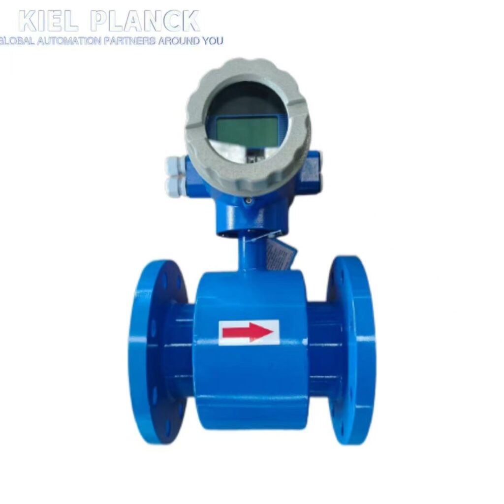
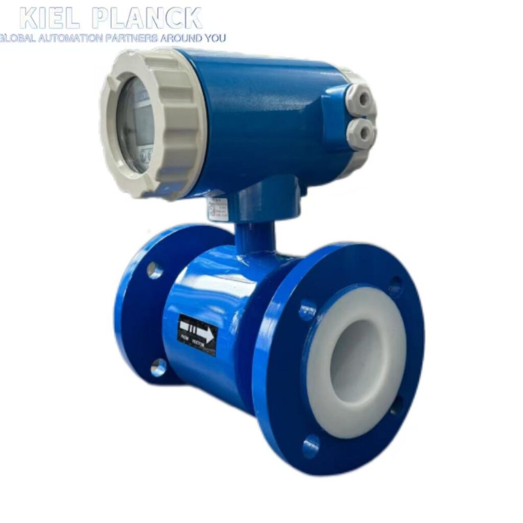
Electromagnetic Flow Meter Selection: 6 Key Steps - Kiel Planck

Scan the QR code to receive more detailed information.

Electromagnetic Flow Meter Selection: 6 Key Steps - Kiel Planck

Share:

More Posts

Pressure Transmitter Accuracy: 0.075% vs. 0.1% - Kiel Planck

Pressure Transmitter Accuracy: 0.075% vs. 0.1%

When selecting an industrial pressure transmitter, accuracy is one of the most important specifications to consider. Many buyers compare transmitters with accuracy ratings of ±0.075% and ±0.1%, assuming that the more accurate model is always the better choice

Vortex Flow Meter Installation for Steam: 5 Common Mistakes - Kiel Planck

Vortex Flow Meter Installation for Steam: 5 Common Mistakes

Vortex Flow Meter Installation for Steam: 5 Common Mistakes

Vortex flow meters are widely used for steam flow measurement in power plants, industrial boilers, food processing, and chemical production. They offer a reliable solution for measuring steam flow when the meter is correctly selected and installed.

However, incorrect installation can cause unstable readings, measurement errors, and unnecessary maintenance.

What should you avoid when installing a vortex flow meter on a steam pipeline? Here are five common mistakes to watch out for.

1. Choosing the Wrong Flow Meter Size

Selecting the correct meter size is essential for accurate steam measurement.

A meter that is too large may operate below its recommended flow velocity, reducing measurement reliability at low flow rates. An undersized meter may experience excessive flow velocity or pressure loss.

Before selecting a vortex flow meter, confirm the following parameters:

Minimum, normal, and maximum steam flow rates

Operating pressure and temperature

Steam pipe diameter

Steam density and operating conditions

Required measurement accuracy

For steam applications, flow rate should be evaluated alongside operating pressure and temperature because these conditions affect steam density.

Selection tip: Choose a meter based on the actual operating range rather than simply matching the existing pipe diameter.

2. Ignoring Upstream and Downstream Straight Pipe Lengths

Vortex flow meters measure flow by detecting vortices generated by a bluff body inside the measuring tube.

Elbows, valves, reducers, and other pipeline components can disturb the velocity profile and affect measurement accuracy.

Insufficient straight pipe lengths may lead to unstable readings or increased measurement errors.

To reduce this risk:

Follow the manufacturer’s recommended upstream and downstream straight pipe lengths.

Consider the type and position of nearby elbows, valves, and reducers.

Avoid installing the meter immediately downstream of components that create strong flow disturbances unless the installation has been specifically evaluated.

Install the sensor in the orientation specified by the manufacturer.

Important: Required straight pipe lengths vary by meter design and upstream piping configuration. Always consult the product manual rather than relying on a universal distance.

3. Installing the Meter Where Condensate Accumulates

Steam pipelines can contain condensate, particularly during startup, low-load operation, or inadequate drainage.

Water accumulation can affect steam measurement and may contribute to unstable readings or mechanical problems.

For saturated steam applications, condensate management is especially important.

Before installation:

Confirm that the pipeline layout supports proper condensate drainage.

Check that steam traps and drainage points are appropriately designed and maintained.

Avoid locations where condensate is likely to collect around the meter.

Follow the manufacturer’s recommendations for horizontal or vertical installation.

For wet steam or applications with significant liquid carryover, assess whether the selected meter is suitable for the actual process conditions.

Selection tip: Correct pipeline drainage and steam quality are essential for dependable steam flow measurement.

4. Ignoring Pressure and Temperature Conditions

Steam pressure and temperature directly affect steam density. These parameters are therefore important when calculating mass flow from volumetric flow.

A vortex flow meter may measure volumetric flow, while mass flow calculation may require additional pressure and temperature measurements or an integrated compensation function.

Without appropriate compensation, changes in operating conditions can cause errors in calculated mass flow.

Before commissioning, verify:

The operating pressure and temperature ranges

Whether the application requires mass flow or volumetric flow

Whether pressure and temperature compensation is necessary

Whether the transmitter supports the required inputs or communication functions

Whether the selected meter is rated for the maximum operating conditions

For saturated steam, pressure and temperature have a defined relationship under equilibrium conditions. For superheated steam, both parameters are generally important for determining density accurately.

Important: Confirm the required compensation method with the manufacturer or process engineer.

5. Overlooking Pipe Vibration and Mechanical Installation

Vortex flow meters detect periodic pressure fluctuations caused by vortex shedding. External mechanical vibration can interfere with the measurement signal under certain conditions.

Steam pipelines may experience vibration caused by pumps, compressors, control valves, unsupported pipe sections, or changing operating conditions.

To minimize potential problems:

Ensure that the pipeline is adequately supported.

Avoid installation locations with excessive mechanical vibration.

Check that flanges, bolts, and gaskets are installed correctly.

Confirm that the meter is aligned with the pipeline.

Verify that the instrument’s vibration limits are suitable for the installation.

If readings become unstable at specific flow rates, investigate both process fluctuations and possible mechanical interference.

Steam Flow Meter Installation Checklist

Before starting the system, review the following checklist:

Item

What to Check

Meter sizing

Minimum, normal, and maximum steam flow

Straight pipe

Manufacturer’s upstream and downstream requirements

Condensate

Drainage, steam traps, and potential liquid accumulation

Pressure and temperature

Operating limits and compensation requirements

Mechanical installation

Pipe support, alignment, and vibration

Commissioning

Wiring, configuration, and output verification

Conclusion

Reliable steam flow measurement depends on more than choosing a suitable vortex flow meter. Correct sizing, sufficient straight pipe lengths, effective condensate management, appropriate pressure and temperature compensation, and proper mechanical installation all contribute to measurement performance.

By avoiding these five common mistakes, you can reduce installation problems and improve the reliability of steam flow measurement in industrial applications.

Looking for a vortex flow meter for steam measurement? Provide your pipe diameter, minimum and maximum flow rates, operating pressure, and temperature. These details will help identify a suitable meter configuration for your application.

Electromagnetic Flow Meter Problems: 3 Common Causes** - Kiel Planck

Electromagnetic Flow Meter Problems: 3 Common Causes**

Electromagnetic flow meters are widely used in water treatment, wastewater management, chemical processing, and other industrial applications. However, problems such as empty pipe alarms, abnormal readings, and excessive measurement errors can affect process monitoring and efficiency.

Monocrystalline Silicon vs. Capacitive Pressure Transmitters: 6 Applications - Kiel Planck

Monocrystalline Silicon vs. Capacitive Pressure Transmitters: 6 Applications

hoosing the right pressure transmitter is essential for accurate measurement and stable industrial operation. Monocrystalline silicon and capacitive pressure transmitters are both widely used in industrial process control, but their performance depends on the measurement principle, process conditions, and application requirements.

Send Us A Message

captcha
Reload

Bitte geben Sie die im CAPTCHA angezeigten Zeichen ein, um sicherzustellen, dass Sie ein Mensch sind.

Email
Email: info@kielplanckprc.com
WhatsApp
WhatsApp Me