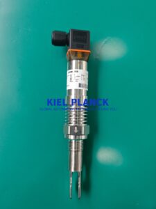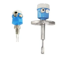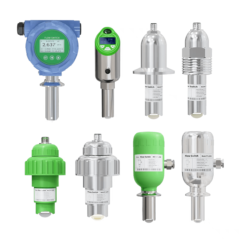
A tuning fork level switch is designed to detect whether a liquid has reached a specified point. If the instrument does not change its output as expected, the problem may involve the process conditions, installation, wiring, or instrument configuration.
A systematic troubleshooting process helps identify the likely cause before replacing the device.
Problem 1: The Output Does Not Change
If the output remains in the same state when the liquid level changes, begin by checking the following:
Is the instrument receiving the correct supply voltage?
Are the electrical connections correct?
Has the liquid actually reached the sensing element?
Is the output connected to a compatible receiving device?
Is the instrument configured for the expected switching logic?
Use the manufacturer’s wiring diagram and testing procedure to verify the installation.
Do not assume that a constant output automatically means the sensing element has failed.
Problem 2: The Switch Gives an Unexpected Signal
An unexpected switching state may result from incorrect wiring, unsuitable process conditions, or an incorrect interpretation of the output logic.
Check the configured fail-safe behavior and determine whether the output is intended to switch when the fork becomes wetted or when it becomes dry.
Also verify whether the connected PLC or relay expects the correct signal type.
Problem 3: The Instrument Works Intermittently
Intermittent operation can have several possible causes.
Check the stability of the power supply and inspect the electrical connections.
Review whether liquid turbulence, process fluctuations, or buildup around the sensing element could affect detection.
If the problem continues, compare the actual process conditions with the manufacturer’s specified operating range.
Problem 4: Deposits Accumulate on the Sensing Fork
Some liquids can leave deposits on the sensing element.
Depending on the material and process, these deposits may interfere with the expected vibration behavior.
Check whether the liquid’s properties are suitable for the selected instrument and follow the manufacturer’s recommended cleaning procedure.
Do not use cleaning chemicals or mechanical methods that could damage the sensing element or compromise material compatibility.
Problem 5: The Switch Fails After Installation
If the switch worked before installation but does not operate correctly afterward, review the installation process.
Potential causes include:
Incorrect wiring
Unsuitable mounting orientation
Mechanical damage during installation
Incorrect process connection
Operating conditions outside the product specifications
Check the instrument and its connected control system systematically rather than replacing components without verification.
A Practical Troubleshooting Checklist
| Check | Action |
|---|---|
| Power supply | Verify the specified voltage |
| Wiring | Compare connections with the wiring diagram |
| Output | Confirm the signal type and switching logic |
| Liquid contact | Check whether the sensing point is actually wetted |
| Installation | Review orientation and mounting position |
| Sensing element | Inspect for deposits or damage when safe |
| Process conditions | Confirm temperature, pressure, and medium compatibility |
| Control system | Verify PLC or relay configuration |
Important Safety Notes
Before inspecting, removing, or cleaning the instrument, assess the process hazards.
Isolate electrical power and follow the required process isolation and depressurization procedures.
If the instrument is installed in a hazardous area, follow the applicable safety and maintenance requirements.
Frequently Asked Questions
Q1: Should I replace the switch if it does not change state?
Not immediately. First check the power supply, wiring, output configuration, liquid contact, and installation conditions.
Q2: Can deposits cause switching problems?
Yes. Depending on the liquid and deposit characteristics, buildup may affect the sensing element.
Q3: What information should I provide to technical support?
Provide the model number, medium, process conditions, supply voltage, wiring configuration, observed output, and a description of the problem.
Conclusion
Effective tuning fork level switch troubleshooting begins with systematic checks of the power supply, wiring, installation, and process conditions. Following the manufacturer’s procedures helps identify the cause and determine whether cleaning, configuration changes, or replacement is necessary.


Scan the QR code to receive more detailed information.