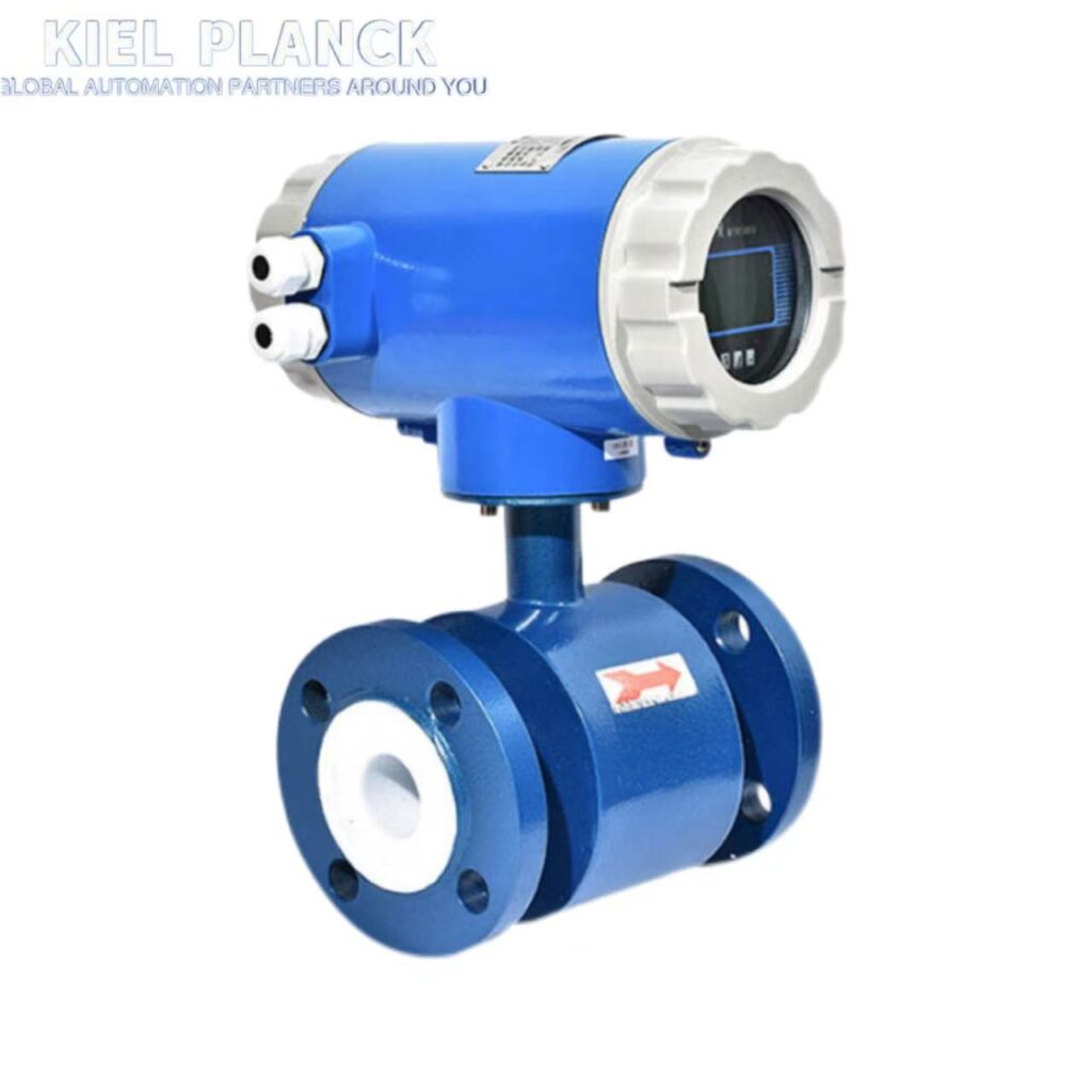
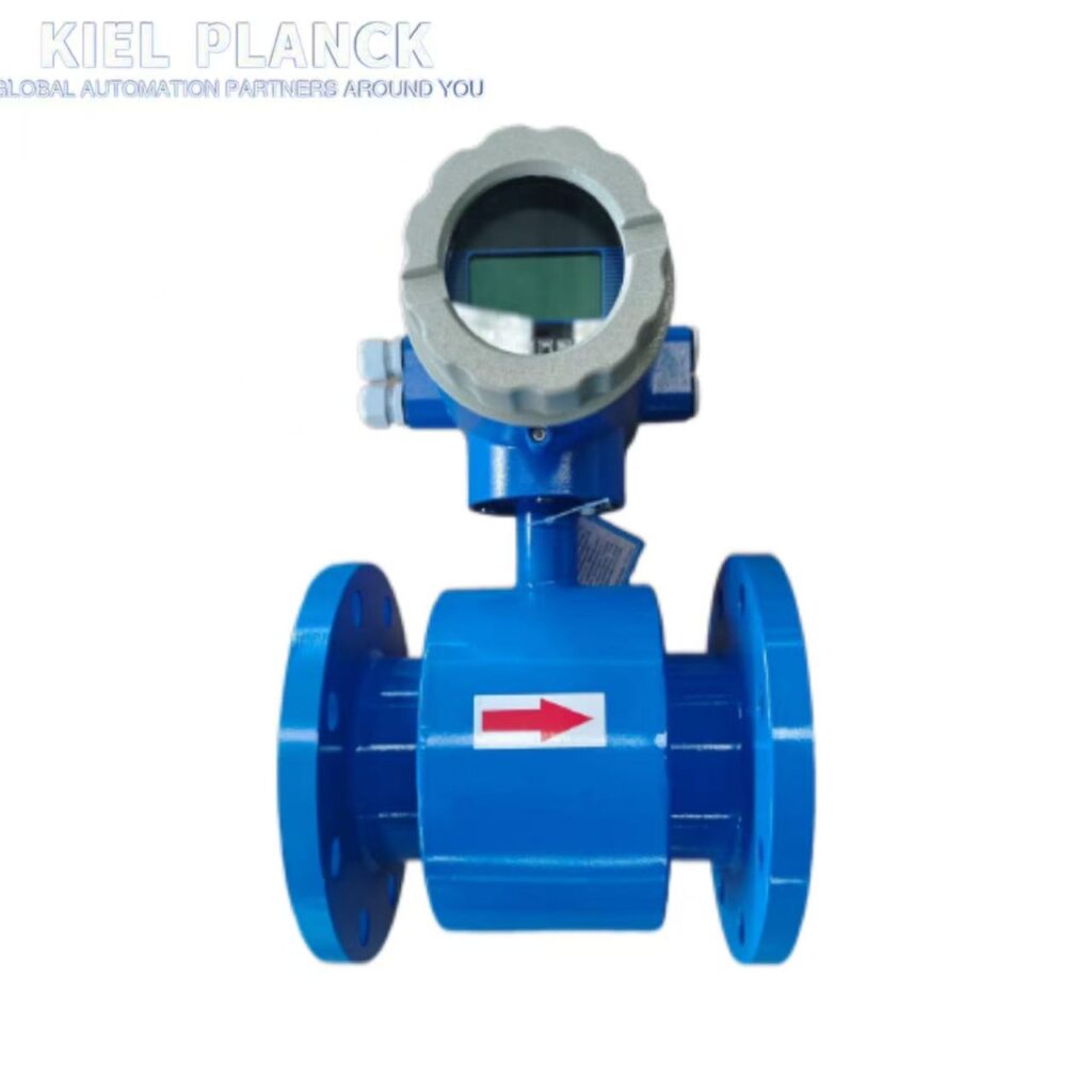
Research on anti-interference of electromagnetic flowmeter
The core of electromagnetic flowmeter anti-interference research is to build a prevention and control system from five layers: interference source, coupling path, equipment body, signal processing and installation and maintenance. The focus is on suppressing power frequency/high frequency radiation, ground loops, and orthogonal/common mode interference, so as to improve the measurement stability and accuracy in complex industrial environments.
I. Sources and Mechanisms of Interference
1. By Coupling Path
Spatial Radiation Interference: Inverters, motors, welding machines, and high-voltage cables generate alternating electromagnetic fields, inducing interference voltage; noise at a distance of 1 meter from the inverter can be 2–3 times that of the normal signal.
Conducted Coupling Interference: Intrusion occurs through power lines, signal lines, and ground loops; interference voltage can reach tens of volts when power cables and signal lines share a conduit.
Ground Loop Interference: Multiple grounding points create potential differences, introducing common-mode noise; this is more likely to occur in insulated pipes/cathode-protected pipes.
2. By Interference Type
Orthogonal Interference (90°): Distributed capacitive coupling between the excitation coil and the electrodes results in a 90° phase difference with the flow signal, prominent in traditional AC excitation.
In-Phase/Common-Mode Interference: Equal-value in-phase noise appears synchronously on both electrodes, mainly at power frequency (50/60Hz), originating from ground current and power supply fluctuations.
Polarization Interference: Electrochemical polarization of the electrode surface under DC excitation generates drift voltage.
Fluid noise: Flow noise and bubble interference in slurry/high-gas-content media.
II. Hardware Anti-interference Design
1. Excitation Technology Optimization
Dual-frequency trapezoidal wave excitation (mainstream): High-frequency (1kHz+) suppresses slurry/flow noise, low-frequency (10–50Hz) stabilizes zero point and reduces noise; error is reduced to ±0.5% compared to single-frequency excitation, and zero-point drift is reduced by 80%.
Symmetrical excitation coil: Geometric/parameter balance reduces orthogonal interference and distributed capacitance coupling.
2. Electromagnetic Shielding and Grounding
Multi-layer shielding structure: Double-layer metal shielding for sensor/converter (copper alloy + low carbon steel), 50Hz power frequency attenuation >40dB, external EMI reduced by 80%+.
Dedicated shielded cable: Twisted pair, double-layer shielding; outer layer grounded at the sensor end, inner layer grounded at a single point at the converter end to avoid ground loops; cable runs through galvanized steel conduit, with a distance of ≥30–50cm from power cable, and shared conduit is prohibited.
Independent Grounding System: Sensors, converters, and pipe flanges are grounded at a common point, with a grounding resistance <4Ω; insulated/cathode-protected pipes are equipped with grounding rings.
3. Structure and Materials
Non-magnetic Housing: Utilizes a low-permeability alloy (e.g., Fe71.6Si13.8B15.6) to constrain magnetostriction and eddy current losses.
Electrode Optimization: Double-helix layout (80mm spacing) reduces magnetic field coupling by 62%; titanium alloy/platinum electrodes improve stability, and a 15μm coating enhances high-frequency interference constraint.
4. Power Supply and Isolation
Redundant Power Supply + EMI Filtering: Dual-channel DC24V automatic switching; input power filter/isolation transformer to constrain high-frequency grid noise.
III. Software Anti-interference Algorithms (Signal Processing)
1. Digital Filtering (Basic)
Mean Filtering: Constrains high-frequency random noise, suitable for stable signals.
Median Filtering: Eliminates pulse/spiking interference, improving stability.
Wavelet Packet + Adaptive Threshold: Increases signal-to-noise ratio from -12dB to +18dB under 500kHz interference, accurately separating flow signals from noise.
Kalman Filtering: Dynamically tracks flow status, reducing error from ±1.5% to ±0.3%, suitable for time-varying interference.
2. Zero-Point Compensation and Fault Tolerance
Automatic Zero-Point Calibration: Real-time elimination of temperature drift, time drift, and polarization voltage effects.
Software Watchdog + Redundancy Check: Automatic reset in case of program crash/freeze; CRC/parity check ensures reliable data transmission.
IV. Installation and Operation/Maintenance Interference Prevention
Site Selection and Isolation: Keep away from frequency converters (≥5m), motors (≥2m), and high-voltage cables (≥3m); avoid areas with turbulent flow, such as bends, valves, and pump outlets.
Fluid Pretreatment: Install an upstream deaerator (to remove air bubbles) and a filter (≤50μm) to prevent electrode contamination and media noise.
Regular Maintenance: Clean electrode fouling every 3–6 months; calibrate annually and check grounding and shielding integrity.
V. Research Hotspots and Trends
Intelligent Anti-interference: Deep learning (CNN) identifies impulse interference with an accuracy of 98.7%, achieving active constraint.
Broadband Anti-interference: Ultra-wideband excitation and multi-scale wavelet fusion cover interference from power frequency to MHz level, adapting to complex operating conditions.
IoT-based Monitoring: Real-time diagnosis of interference type and intensity, remote early warning, and parameter self-optimization.
Summary in One Sentence
Electromagnetic flowmeter anti-interference research focuses on **”source constraint — path isolation — body reinforcement — signal purification — operation and maintenance support”**. Through dual-frequency excitation, shielded grounding, intelligent filtering, and standardized installation, errors in strong interference environments can be controlled within ±0.5%, meeting the requirements of industrial and trade metering.