Installation of intelligent electromagnetic flowmeter
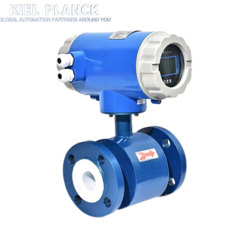
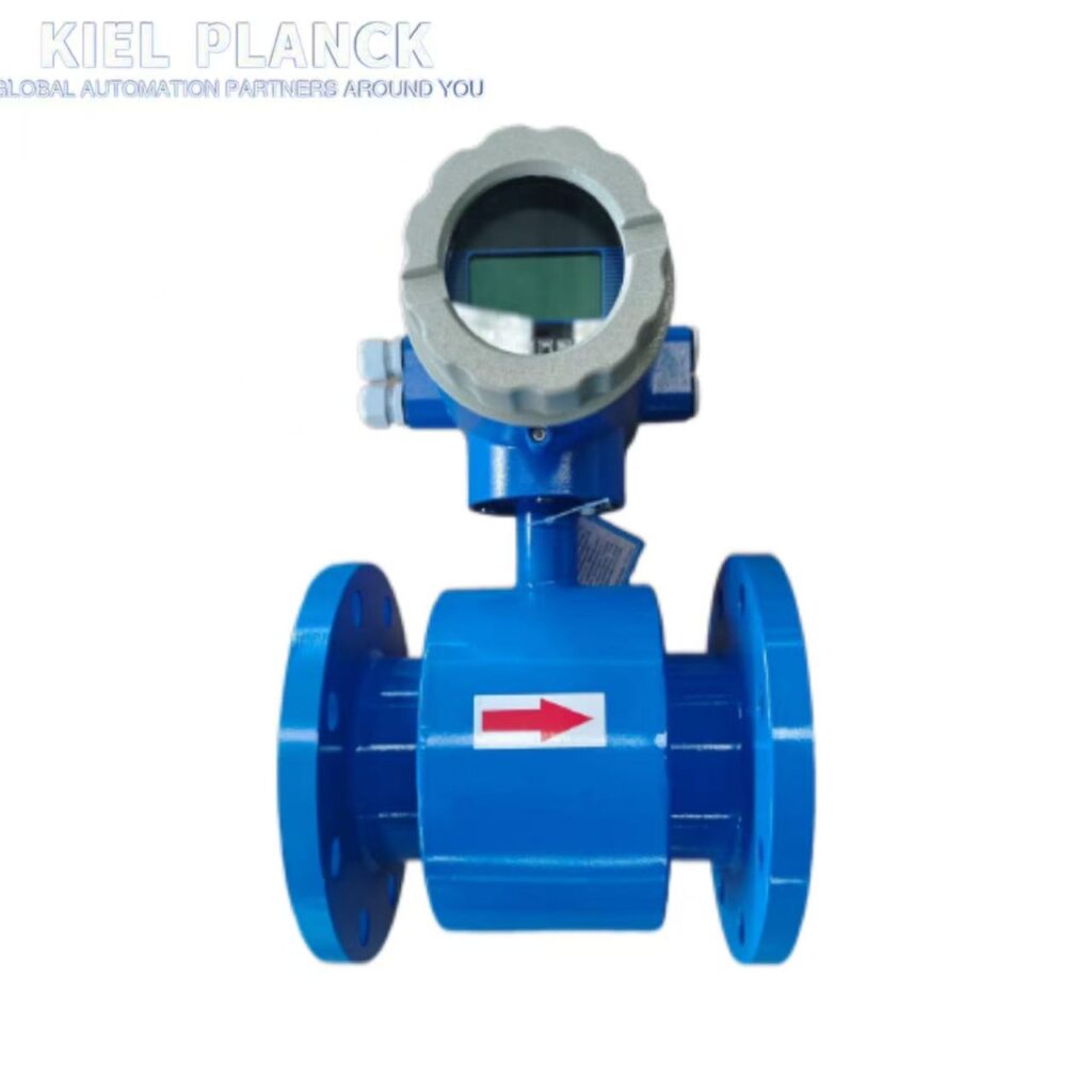
The installation of intelligent electromagnetic flowmeters must strictly follow key points such as location selection, straight pipe section requirements, installation direction, and grounding specifications to ensure measurement accuracy and long-term stable operation of the equipment.
I. Installation Location Selection
1. Medium Requirements
The pipeline must be completely filled with liquid to prevent air bubbles or sediment from affecting measurement accuracy. If the pipeline is not completely full, the flow meter should be installed at the lowest point of the U-shaped pipe or a siphon design should be used.
Avoid Air Bubble Interference: When the fluid contains air bubbles, the flow meter should be placed upstream of the valve to prevent pressure reduction and the generation of air bubbles.
Avoid Negative Pressure Environments: The flow meter should be installed at the pump outlet, not the inlet, to prevent negative pressure from damaging the lining (especially PTFE material).
2. Interference Source Avoidance
Keep Away from Flow-Disrupting Equipment: Keep the flow meter as far away as possible from pumps, valves, elbows, and other equipment to avoid interference with the measurement.
Avoid Strong Electromagnetic Interference: The installation location should be far away from high-power motors, transformers, frequency converters, and other strong magnetic field sources (recommended distance ≥ 5 meters).
Avoid Vibration Sources: Avoid strong vibration sources. If unavoidable, install fixed supports on both sides of the flow meter (distance ≤ 3 times the pipe diameter).
II. Straight Pipe Section Requirements
1. Standard Straight Pipe Section Length
Upstream Straight Pipe Section: At least 5 times the pipe diameter (5D), 10D-15D recommended to ensure fluid stability.
Downstream Straight Pipe Section: At least 3 times the pipe diameter (3D), 5D recommended to reduce eddy current effects.
2. Special Case Handling
With turbulent components: If there are elbows, valves, or other turbulent components upstream, the straight pipe section should be extended to 15D-20D.
With limited space: A flow rectifier (such as a honeycomb flow rectifier) can be installed to shorten the required straight pipe section.
Measuring mixed media: The distance between the mixing point and the flow meter should be ≥30D; otherwise, the display may be unstable.
III. Installation Direction and Position
1. Vertical Installation
Recommended flow direction: Fluid flows from bottom to top, ensuring the measuring tube is always filled with the medium.
Applicable scenarios: Particularly suitable for liquid-solid two-phase flows (such as mud, sewage), allowing for uniform lining wear and extending service life.
2. Horizontal Installation
Electrode Position: Ensure both electrodes are horizontal to prevent air bubbles at the top or sediment at the bottom from affecting the measurement.
Installation Recommendation: Install at a slightly elevated point in the pipeline, avoiding installation at the highest point.
3. Special Locations
Open Discharge Pipelines: Install at the lowest point of the pipeline, avoiding installation on vertical pipes with rear-end venting.
Large Drop Pipelines: If the drop exceeds 5m, an air vent valve should be installed downstream of the flow meter.
IV. Grounding Specifications
1. Necessity of Grounding
Eliminating Interference: Reliable grounding conducts interference currents, creating a stable measurement environment for the electrodes and preventing a surge in measurement errors.
Safety Protection: Prevents damage to internal circuits from lightning strikes or electrostatic discharge (breakdown voltage can exceed 1kV).
2. Grounding Implementation Methods
Metal Pipelines: Connect the sensor flange to the mating flange of the pipeline with a conductor, using a copper core grounding wire with a cross-sectional area ≥4mm².
Non-metal Pipelines: Achieve equipotential bonding by installing a grounding ring. The grounding ring material must match the dielectric properties.
Grounding Resistance: Must be ≤10Ω and cannot share a grounding line with other equipment to prevent ground loop interference.
V. Environmental Requirements
1. Temperature and Humidity
Ambient Temperature: Should be within the range of -20℃ to 60℃, avoiding high-temperature radiation sources (such as boilers and steam pipes).
Relative Humidity: Should be less than 85%, avoiding humid and waterlogged environments.
2. Protective Measures
Outdoor Installation: A rain shelter or sunshade must be erected to prevent exposure to sunlight and rain.
Corrosive Environment: Avoid installation in environments containing corrosive gases. If this cannot be avoided, ventilation equipment must be installed and a corrosion-resistant flow meter must be used.
VI. Special Operating Conditions
1. Large Diameter Flowmeter Installation
Underground Installation: A concrete pit should be prepared, ensuring sufficient space for movement. A steel conduit for cable laying should be buried in the side wall, with a rainproof cover and a drain pipe at the bottom.
Easy Disassembly and Assembly: The sensor should be placed on a base, with a flexible expansion joint installed downstream for easy maintenance.
2. Signal Transmission Standards
Cable Selection: Dedicated shielded wire should be used. The recommended signal cable length is ≤30m.
Wiring Requirements: Signal cables should not be run parallel to power lines; they should be spaced at least 15cm apart and run separately in metal conduits.
3. Valve Installation Location
Control Valves: Should be installed on the measured pipe upstream of the flowmeter.
Regulating Valves: Should be installed downstream of the flowmeter to avoid flow fluctuations within the measuring pipe.
VII. Post-Installation Inspection and Maintenance
1. Pre-Commissioning Inspection
Comprehensive Inspection: Confirm that all components are installed correctly and securely.
Power-on check: Observe whether the instrument display is normal and whether there are any abnormal alarms or indications.
Zero-point calibration: Perform zero-point calibration with the pipeline filled with medium and completely stationary. The stabilization time should be ≥30 seconds.
2. Regular Maintenance
Inspection Frequency: Check grounding resistance, flange sealing, and cable connections quarterly.
Cleaning Cycle: Calibrate once a year for ordinary media; calibrate every 3-6 months for corrosive media.
Troubleshooting: If output fluctuates significantly, check for electromagnetic interference or pipeline vibration; if the flow rate reading is low, check for electrode contamination or lining damage.
By strictly following the above installation specifications, the measurement accuracy of the intelligent electromagnetic flowmeter can be ensured to reach ±0.5% (refer to ISO 9104 standard), and the service life of the equipment can be significantly extended. In practical applications, it is recommended to refer to the manufacturer’s installation instructions for adjustments based on specific operating conditions to achieve the desired measurement results.