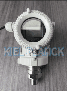
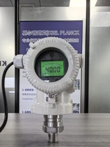
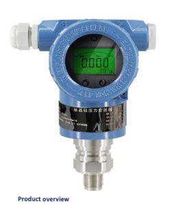
However, field maintenance personnel commonly encounter a persistent problem: even after rigorous zero and full-scale calibration, the measured level value always maintains a fixed or floating slight deviation from the actual liquid level. Most users attribute this error to instrument accuracy failure or calibration mistakes, while ignoring inherent systematic errors caused by working condition changes and installation defects. This article analyzes the core causes of persistent level measurement deviations of DP transmitters, including variable medium density, wet leg liquid fluctuation, capillary temperature drift and unreasonable damping settings. It summarizes practical field correction methods to eliminate residual errors, providing targeted solutions for accurate and stable DP level monitoring.
1. Introduction
DP level measurement follows the classic hydrostatic formula ΔP=ρgh, which means level data is theoretically linear and completely accurate under fixed density and stable pressure conditions. In laboratory environments with constant temperature and static media, DP transmitters can achieve ideal measurement accuracy. Nevertheless, actual industrial tanks are always affected by temperature changes, medium concentration fluctuation, pipeline residual liquid and pressure disturbance. These invisible variable factors continuously interfere with pressure signal conversion, resulting in unavoidable slight deviations. Unlike sudden instrument faults, this kind of persistent minor error is cumulative and systematic, which cannot be completely eliminated by simple on-site recalibration. Clarifying the hidden error sources is the key to solving long-term inaccurate level measurement problems.
2. Core Causes of Persistent Level Deviation
The first and most common cause is variable medium density. Factory calibration and parameter setting adopt standard density values at room temperature. In actual operation, medium temperature rise or concentration change will directly modify liquid density. Since level height is inversely proportional to density under the same hydrostatic pressure, even a small density fluctuation will produce consistent measurement deviation. For oil, chemical solutions and mixed media, density drift is particularly obvious with temperature variations, leading to permanent offset between displayed level and real liquid height without density compensation.
Second, unstable wet leg and impulse tube conditions trigger fixed errors. For sealed tank DP measurement, the low-pressure wet leg is designed to balance tank static pressure. However, long-term operation easily causes liquid evaporation, condensate accumulation, tiny bubbles or dirt deposition in the impulse pipeline. These subtle changes alter the initial pressure balance state. After each startup and shutdown, the residual liquid volume in the pipeline cannot remain consistent, resulting in different zero offset values and persistent level deviation after calibration.
Third, capillary temperature drift and filling fluid thermal expansion induce systematic errors. For remote diaphragm seal DP transmitters, filling oil inside capillaries expands or contracts with ambient and medium temperature changes. Uneven temperature distribution between high-pressure and low-pressure sides breaks pressure balance, generating additional zero drift. Seasonal temperature alternations make this deviation more obvious, causing accurate winter readings but offset summer data, or vice versa.
Fourth, improper damping and response parameter matching leads to visual deviation. Many field technicians set excessive damping to avoid data jitter caused by liquid turbulence. Excessively large damping coefficients delay real-time data response, making the displayed level always lag behind the actual liquid level change. Conversely, insufficient damping retains fluctuation noise, resulting in unstable average values and persistent minor errors in static state.
3. Field Optimization and Error Elimination Methods
To eliminate long-term slight level deviations, targeted systematic optimization is required rather than repeated blind calibration. First, install real-time temperature compensation modules and modify DCS calculation logic to correct density errors dynamically according to medium temperature changes. Second, regularly exhaust and flush impulse pipelines to stabilize wet leg liquid level and eliminate bubble interference, ensuring consistent pressure balance conditions before calibration. Third, select high-temperature stable filling fluid and optimize capillary laying to avoid temperature difference stress. Finally, set graded damping parameters according to working condition turbulence to balance data stability and response sensitivity.
4. Conclusion
The persistent slight deviation of DP transmitter level measurement is rarely caused by instrument quality problems or calibration failure, but originates from systematic errors including variable medium density, unstable wet leg pressure balance, capillary temperature drift and unreasonable parameter configuration. These hidden industrial working condition factors cannot be eliminated by conventional zero and span calibration. Industrial maintenance teams must abandon the simple calibration troubleshooting mindset, adopt temperature and density compensation, standardized pipeline maintenance and precise parameter debugging. Comprehensive systematic optimization can fundamentally reduce residual errors and achieve highly consistent and stable liquid level measurement for industrial sealed tanks.
Scan the QR code to receive more detailed information.