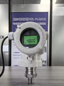
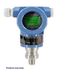
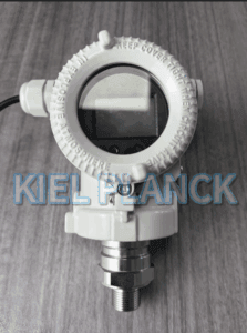
It also introduces temperature coefficient indicators, heat dissipation accessories and material limits for wetted components. By interpreting these parameters correctly, engineers can select suitable pressure sensors for high-temperature hydraulic oil, avoid over-temperature induced measurement deviation and premature failure, and maintain reliable pressure feedback for hydraulic closed-loop control systems.
Introduction
Hydraulic oil temperature rises continuously during continuous operation of hydraulic stations. In servo hydraulic presses, test benches and high-load hydraulic equipment, oil temperature can easily reach 120°C or even higher. Pressure sensors directly exposed to hot oil face combined thermal stress on diaphragms, O-rings and internal electronic chips. Datasheets contain multiple temperature-related parameters, which are frequently misread by procurement and design teams. Many users only focus on a single maximum temperature number, without distinguishing whether this value applies to oil medium or sensor electronics. A sensor that tolerates high medium temperature may still lose accuracy if the electronic housing exceeds its ambient temperature rating.
The first critical parameter is medium temperature limit. This value defines the maximum fluid temperature that the wetted parts including diaphragm, pressure port and seals can withstand. It is determined by the metal alloy of the sensing diaphragm and elastomer seal material. For mineral hydraulic oil at 120°C or below, FKM (Viton) seals paired with 17-4PH or 316L stainless steel diaphragms are acceptable. If oil temperature rises to 150°C or higher, standard rubber seals degrade rapidly, and welded diaphragm structures must be adopted. It is worth noting that medium temperature describes the fluid touching the sensor front end, not the temperature of the transmitter’s electronic housing. Some high-temperature sensors adopt a cooling tail or heat sink structure. This design allows hot oil to contact the diaphragm, while reducing heat transfer to electronic circuits. In this case, the medium temperature limit can be far higher than the ambient temperature rating of the electronics.
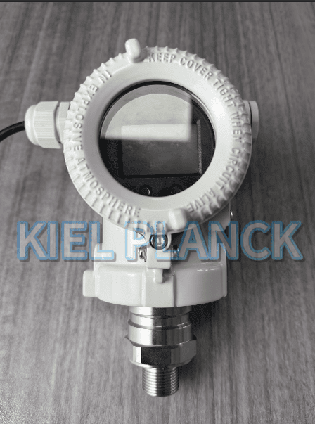
The second parameter is ambient operating temperature. This specifies the temperature range for the transmitter’s circuit housing. Electronic components, circuit boards and solder joints have strict temperature limits. Even if the diaphragm can endure 150°C oil, the electronic module usually cannot operate above 80°C. If heat conduction raises the housing temperature beyond this limit, the chip will suffer unstable output or permanent burnout. When hot oil measurement cannot be avoided, install a heat dissipation extension or remote diaphragm to isolate electronics from high heat.
Third, the compensated temperature range. This is the range within which the manufacturer guarantees the stated accuracy. Within this band, built-in digital compensation circuits suppress thermal drift. Outside the compensated range but still within operating limits, the sensor can physically survive, but additional temperature error will appear. This extra error is quantified by temperature coefficient, including zero temperature effect and span temperature effect, expressed in %FS/°C. For example, a zero drift coefficient of 0.02%FS/°C means every 10°C temperature rise brings an additional 0.2% full-scale zero offset. Many engineers overlook this point: a sensor may survive high temperature physically, yet its measurement error becomes too large for control use outside the compensated range.
Material limits are another hidden factor when checking temperature parameters. At elevated oil temperature, hydraulic oil additives become chemically more active. High temperature accelerates seal swelling and aging. A seal suitable for 80°C mineral oil may fail quickly at 130°C, even if the temperature rating is nominally satisfied.
There are typical mistakes in reading datasheets. One common error is equating medium temperature limit with compensated temperature range. Another mistake is ignoring peak temperature: short temperature spikes can damage seals or diaphragms even if the average temperature stays within limits. When reviewing specifications, users also need to check long-term stability at elevated temperature, not only static accuracy at room temperature.
For field deployment, heat reduction methods help reduce thermal load. A cooling fin or capillary can lower heat transfer. Flush diaphragm designs reduce dead volume and avoid hot oil stagnation. Users also need to perform zero recalibration after the system reaches stable high temperature, to compensate for minor thermal offset.
Conclusion
For pressure sensors measuring high-temperature hydraulic oil, three temperature specifications on datasheets must be checked separately: medium temperature limit, ambient operating temperature and compensated temperature range. Medium temperature determines whether wetted metal and seals can resist hot hydraulic oil. Ambient temperature protects internal electronic circuits. The compensated temperature range defines the scope where the published accuracy and temperature coefficient are guaranteed. Engineers should never judge high-temperature suitability from only one temperature value. The temperature coefficient and wetted material compatibility also play vital roles. Where oil temperature exceeds standard sensor limits, heat dissipation structures or remote diaphragm configurations are required. Correct interpretation of datasheet temperature parameters prevents thermal drift, seal degradation and premature sensor failure, delivering stable and accurate pressure measurement for high-temperature hydraulic oil applications.
Scan the QR code to receive more detailed information.