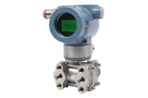
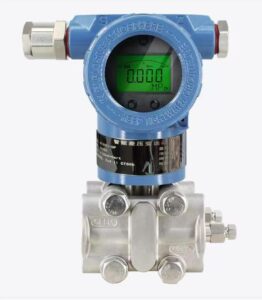
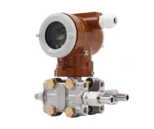
Unlike mechanical pressure switches that rely on spring adjustment, electronic models use digital menus to configure switch points, hysteresis and delay parameters. Many field technicians are familiar with mechanical switch tuning but struggle with digital configuration, leading to incorrect setpoints, output chattering or false alarms. This article introduces the standard workflow for setting pressure thresholds on hydraulic electronic pressure controllers, explains key parameters including switch point, reset point, hysteresis and time delay, and lists common setup mistakes encountered in hydraulic environments. Step-by-step configuration guidance helps operators complete commissioning correctly, avoid unstable switching caused by hydraulic pulsation, and ensure reliable pressure interlock protection for hydraulic power units.
Introduction
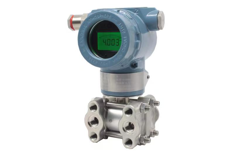
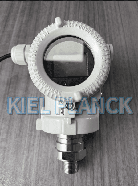
Hydraulic electronic pressure controllers integrate solid-state pressure sensing elements, microprocessors and local digital displays. They can provide continuous pressure readings and programmable switching outputs for PLC or relay logic. The biggest advantage over traditional mechanical pressure switches is flexible parameter configuration. Users can define multiple trigger points and tune hysteresis without disassembling the device. However, improper setup often causes operational problems. Typical symptoms include frequent false triggering from pressure ripple, failure to cut off pressure at the target value, or no reset after pressure drops. These issues are often misjudged as hardware faults, while the root cause lies in incorrect parameter setup.
Before starting adjustment, technicians should complete pre-checks. Confirm the controller’s pressure range matches the hydraulic system working pressure. Verify wiring for power supply and switching output; loose wiring can create abnormal signals. Check that the installation is secure and the medium compatibility fits hydraulic oil. The system pressure should be controllable and can be slowly raised or lowered during calibration. It is strongly recommended to perform setpoint adjustment during offline commissioning rather than during full-load production operation, to prevent unexpected equipment actions.
The core adjustable parameters include switch setpoint, reset point, hysteresis and switch delay. The setpoint is the pressure value that activates the switching output. The reset point is the pressure where the output returns to its original state. Hysteresis, also known as dead band, is the pressure difference between setpoint and reset point. In hydraulic circuits, pressure pulsation from pumps will cause rapid small fluctuations around the target threshold. If hysteresis is set too narrow, the switch will repeatedly turn on and off rapidly, known as chattering, which damages relays and contactors. Time delay is another useful parameter; it filters transient pressure spikes by requiring the pressure condition to persist for a preset duration before triggering the switch.
The standard adjustment procedure follows four steps. First, enter the parameter menu via the physical buttons on the controller. Most products use short-press and long-press combinations to unlock configuration, as menus are usually password-locked to prevent unintended modification. Second, select the switching channel; many controllers support two independent switch outputs for high-pressure protection and low-pressure warning. Third, input the target setpoint and hysteresis value. For example, if overpressure protection needs to trigger at 210 bar and reset at 190 bar, the hysteresis equals 20 bar. The hysteresis must be larger than the amplitude of natural pressure pulsation of the hydraulic circuit. Fourth, set the switch delay time, commonly 0.1 to 2 seconds for hydraulic systems, to filter millisecond-scale pressure hammer spikes. After saving parameters, exit the menu and return to measurement display mode.
Once parameters are saved, perform a live functional test. Slowly ramp up hydraulic pressure and observe whether the digital display and switching output trigger exactly at the preset value. Then reduce pressure and verify the reset action. If chattering occurs, increase hysteresis or extend delay time. If trigger pressure deviates significantly from the target value, recheck the zero point of the controller. Zero drift caused by over-torque installation or temperature changes will affect setpoint accuracy, so zero calibration should be completed before adjusting thresholds.
Several common pitfalls need attention. Some technicians confuse the setpoint direction: normally open and normally closed outputs behave oppositely when pressure crosses the threshold. Mixing up NO and NC logic leads to reversed protection actions. Another mistake is setting hysteresis too small, ignoring hydraulic pulsation characteristics. Users also sometimes modify parameters while the hydraulic system is running under heavy load, which may cause sudden pump shutdown or actuator movement and create safety risks. In addition, after replacing hydraulic oil or carrying out sensor maintenance, re-verification of setpoints is required.
Conclusion
Adjusting setpoints for hydraulic electronic pressure controllers mainly involves unlocking the menu, selecting switch channels, configuring trigger points, hysteresis and time delay, and conducting on-site pressure testing. Hysteresis and delay settings are especially critical for hydraulic applications to suppress false triggering caused by pump pulsation and pressure hammer. Operators must distinguish normally open and normally closed output logic, and complete zero calibration before parameter setup. Never tune parameters during high-load operation to avoid safety hazards. Following this standard configuration workflow ensures accurate and stable switching actions, prevents chattering and false alarms, and delivers reliable pressure interlock protection for hydraulic power units.
Scan the QR code to receive more detailed information.