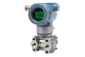
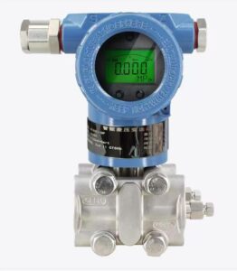
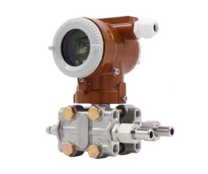
Unlike analog 4–20mA signals, PNP and NPN outputs define the direction of current flow, which must match the sink or source requirements of the receiving PLC digital input module. This article clarifies the working principles of PNP and NPN outputs, compares their wiring schemes, summarizes typical wiring mistakes in hydraulic station installation, and provides on-site verification steps. Correct identification and wiring prevent electrical faults and unintended machine motion, ensuring reliable pressure interlock, pump unloading and alarm functions for hydraulic power units.
Introduction
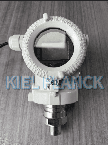
Hydraulic electronic pressure controllers integrate pressure measurement and programmable switch outputs to realize overpressure protection, low-pressure alarm and pump unloading. Their digital switching outputs are mostly PNP or NPN open-collector signals, designed to connect with PLC digital inputs or relay coils. Both types can complete on-off pressure triggering tasks, but their current flow directions are opposite.
A common misunderstanding is that PNP and NPN are just different names for the same switch function. In reality, the distinction lies in which side of the circuit the transistor connects. Mixing them up does not simply result in failure to trigger alarms; in the worst case, it keeps hydraulic relays continuously energized or causes sudden actuator movement, creating serious safety risks during machine commissioning.
NPN output is also known as sinking output. The NPN transistor connects the signal line to the 0V ground side when activated. When the pressure reaches the set threshold, the output pin pulls the signal wire down to ground. The PLC input terminal needs to be connected to the positive 24V DC supply through an internal or external pull-up resistor. In short, NPN receives current into the controller. This output type is widely adopted in many European and older control cabinets.
PNP output is called sourcing output. When the pressure condition is met, the PNP transistor connects the signal pin to the positive 24V DC power rail, sending voltage out to the receiving terminal. The PLC input must be wired to 0V. PNP outputs supply current from the controller to the input module. It has become the mainstream choice for many modern Asian PLC systems.
The first critical rule: the PLC input type must match the controller output. Sourcing PLC inputs require PNP signals, while sinking PLC inputs work with NPN. If a PNP controller is wired to a sinking PLC input without modification, the input will never detect the trigger signal. Conversely, using an NPN device on a sourcing input may lock the signal in an always-active state.
Several typical wiring errors often appear on hydraulic sites. The most frequent mistake is directly replacing an old NPN pressure controller with a PNP model without modifying PLC side wiring. After replacement, the alarm or unloading function fails completely, and technicians may wrongly suspect the new controller is defective. The second error is connecting the switching output directly to a relay coil without considering voltage polarity. Incorrect wiring prevents relay pull-in, or keeps the relay energized all the time. The third mistake is shared ground interference: multiple switch outputs share messy cable routes, causing false triggering.
Before wiring, engineers should confirm three items from the datasheet: output type, maximum load current and voltage range. Do not exceed the rated load; excessive current will burn the transistor inside the pressure controller. The power supply for the controller and PLC should use the same 0V reference. If different power supplies are used, potential differences may cause unstable switching and signal noise.
After wiring, perform a static test before starting the hydraulic pump. Keep the hydraulic system depressurized first. Simulate pressure change either by applying calibration pressure or adjusting the setpoint to trigger the switch. Observe the PLC input status indicator or relay action. If no response occurs, double-check whether PNP/NPN matches the input module, rather than immediately increasing hydraulic pressure for live testing. Live testing with wrong wiring can trigger unexpected pump unloading or pressure cutoff, which may hurt operators or damage tooling.
Another point to note: some electronic pressure controllers support both PNP and NPN via menu selection. Users still need to set the correct mode in the controller menu and match the PLC input. Even if the hardware supports both types, mismatched software settings create the same failure.
Conclusion
PNP and NPN outputs for hydraulic electronic pressure controllers differ fundamentally in current direction: NPN sinks current to ground, while PNP sources 24V voltage to the receiving terminal. The output type of the pressure controller must match the sink/source configuration of the PLC digital input. Improper wiring leads to missing pressure signals, permanently activated outputs and dangerous unintended hydraulic movement. Before installation, technicians must confirm output type on datasheets and check PLC input specifications. Static functional testing without hydraulic pressure is mandatory after wiring. Correct PNP/NPN matching ensures reliable pressure interlock and alarm signals, protects PLC modules, and eliminates safety hazards caused by reversed switching logic on hydraulic power stations.
Scan the QR code to receive more detailed information.