

1. Industry Pain Points of Metallurgical Gas Measurement
- Blast Furnace Gas (mixed CO, CO₂, dust & tar)
High dust, tar condensation, large temperature fluctuation, unstable gas composition; orifice plate, vortex meters are easy to block, require frequent cleaning and extra temperature & pressure compensation, leading to big metering deviation of gas recovery and energy consumption accounting.
- Oxygen Pipeline (high-purity oxidizing gas)
Strict explosion-proof requirement; low to medium flow range changes sharply during furnace start-stop; conventional differential pressure meters have narrow turndown ratio and fail tiny flow capture.
- Nitrogen (shielding & purging gas)
Long-distance large-diameter pipelines, extremely low standby flow, severe pipeline vibration; many meters lose accuracy under near-zero flow conditions.
- Universal troubles: extra compensation cost, high pressure loss, short service life, complicated offline calibration, difficult digital interconnection with furnace control systems.
2. Core Advantages of Thermal Gas Mass Flow Meters for Metallurgical Gas
- Direct mass flow measurement
No extra transmitters or compensation algorithms; stable data output amid furnace load temperature/pressure fluctuations, accurate for energy balance settlement.
- Ultra-wide turndown ratio up to 1:100~1:1000
Detect gas velocity as low as 0.1 Nm/s; covers tiny standby nitrogen purge flow and full-load high flow of blast furnace gas simultaneously.
- Low pressure loss & non-clogged probe design
Inserted dual RTD sensor with smooth anti-tar coating; hardly blocked by BFG dust and tar, far less maintenance frequency than orifice meters.
- Strong anti-vibration & long service life
No moving mechanical parts; shock-absorbing bracket matching metallurgical pipeline vibration environment, less zero drift.
- Customizable anti-explosion & high-temperature structure
Ex d IIC explosion-proof grade for oxygen & blast furnace gas hazardous areas; high-temperature probe supports medium temp up to 180°C for hot raw gas pipelines.
- Diversified digital communication
Built-in 4–20mA, HART, RS485 Modbus-RTU; seamless docking with blast furnace DCS, energy management and intelligent furnace combustion control system.
3. Targeted Matching Scheme for Three Metallurgical Gases
3.1 Blast Furnace Gas Measurement (Large-Diameter Raw Gas Pipeline)
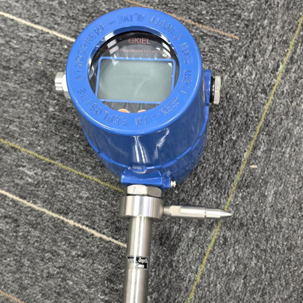
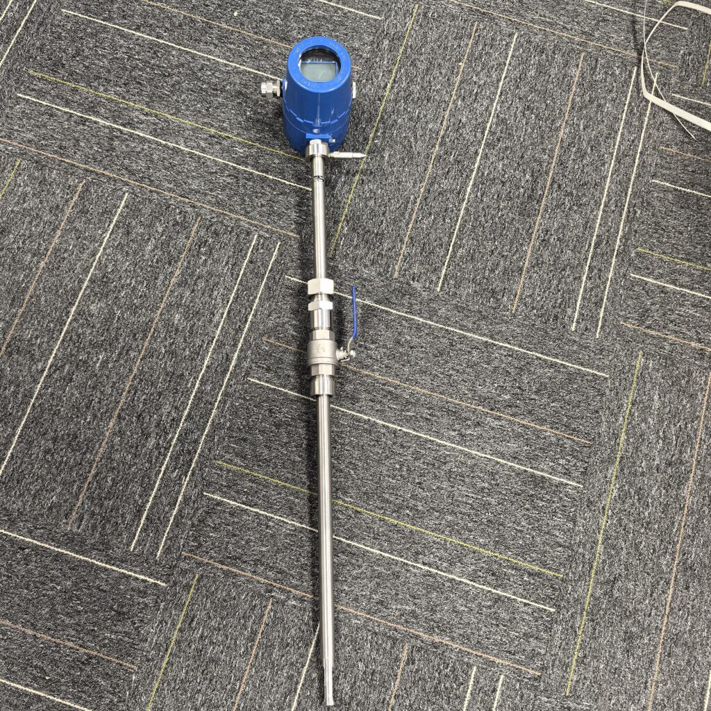
- Model selection: Insertion thermal mass flow meter (DN300~DN3000 pipeline); integrated anti-fouling coated sensor, 316L stainless steel probe, explosion-proof transmitter.
- On-site optimization:
- Install primary filter before sensor to reduce heavy tar & dust adhesion; set monthly automatic zero calibration cycle.
- Reserve upstream ≥10D straight pipe, downstream ≥5D; add flow straightener if elbows/tees are close by.
- Support multi-component mixed gas calibration input according to real-time BFG composition to eliminate heat capacity deviation.
- Application value: Accurate statistical of by-product gas recovery volume, optimize heating furnace air-fuel ratio, cut fuel cost and carbon emission.
3.2 Pure Oxygen Measurement (Combustion Supporting Pipeline)
- Model selection: Inline pipe-type thermal mass flow meter (DN15~DN200); oxygen-specific calibration, fully sealed explosion-proof structure, no oil lubricant inside sensor to avoid oxidation risk.
- On-site optimization:
- Strict pipeline degreasing before installation; isolate oxygen pipeline from high-temperature furnace body with heat insulation cover.
- Real-time flow interlock with blast furnace tuyere control valve; rapid response to adjust oxygen injection volume during smelting load shift.
- Application value: Precise oxygen-iron ratio control, reduce iron loss and extend blast furnace campaign life.
3.3 Nitrogen Measurement (Shielding, Purging & Stirring Gas)
- Model selection: Insertion thermal meter for large nitrogen main pipe; compact inline type for small branch purging pipelines; low-flow high-sensitivity sensor for standby trace nitrogen flow.
- On-site optimization:
- Shock absorption fixing for long-distance vibration-prone nitrogen trunk lines.
- Set low-flow alarm to detect pipeline micro-leakage and avoid nitrogen waste.
- Application value: Save inert gas consumption, stable molten steel quality by consistent nitrogen bottom stirring flow control.
4. Standard Installation & Rapid Zero Calibration Specification
Installation Rules
- Avoid mounting near pumps, elbows, reducers and control valves; guarantee sufficient straight pipe length.
- Horizontal pipeline installation: sensor probe align with pipe central axis; prevent liquid condensate soaking the RTD probe.
- Hazardous oxygen & BFG zones: adopt flameproof junction box, grounded transmitter and explosion-proof cable gland.
On-Site Zero Drift Calibration Flow
- Fully close front & rear cut-off valves, open bypass to ensure complete zero gas flow through the sensor; preheat instrument for 10–15 mins for thermal balance.
- Enter calibration menu via local LCD or HART handheld communicator, start auto-zero sampling for 30–60 seconds without pipeline vibration.
- Save new zero baseline data, keep no-flow status and verify reading near zero; repeat calibration if residual offset exists.
- Restore normal pipeline gas supply and monitor low-flow data stability.
5. Intelligent Control System Integration Solution
- Real-time mass flow data upload to metallurgical DCS platform; realize closed-loop linkage control of BFG supply, oxygen enrichment and nitrogen shielding.
- Equipped with flow cumulative function: automatically generate daily/monthly gas consumption reports for energy audit and cost accounting.
- Remote fault diagnosis: transmit probe fouling alarm, zero drift prompt and over-temperature signal via Modbus; realize predictive maintenance to reduce unplanned shutdown.
6. Field Application Benefits Summary
- Cut instrument maintenance workload by over 70% compared with traditional differential pressure flow meters, eliminate frequent disassembly cleaning for blast furnace gas pipelines.
- Improve gas metering accuracy within ±1.5% FS; stable measurement under ultra-low flow and fluctuating working conditions.
- Reduce overall gas energy consumption by optimizing furnace air-fuel ratio, supporting iron & steel enterprises to complete double-carbon energy-saving transformation.
- One set of instrument platform covers blast furnace gas, oxygen and nitrogen measurement, unify spare parts and reduce procurement cost.
Short Version for Product Brochure / LinkedIn Post
Thermal Mass Flow Meter Solution for Metallurgical Blast Furnace Gas, Oxygen & Nitrogen
Conventional flow meters suffer clogging, big deviation and high maintenance cost under steel plant harsh conditions. Our thermal gas mass flow meter directly measures mass flow without temperature & pressure compensation, featuring 1:1000 wide turndown ratio, anti-tar/dust probe and explosion-proof design.
Custom insertion/inline models for large blast furnace gas trunk, pure oxygen combustion pipeline and nitrogen shielding line. Support on-site fast zero calibration and Modbus DCS interlock, achieving precise gas flow control, energy consumption statistics and intelligent furnace combustion optimization for iron & metallurgy production.
Scan the QR code to receive more detailed information.





