

This paper systematically expounds on the working mechanism of straight pipe sections for ultrasonic flowmeters, clarifies the standard length requirements of upstream and downstream straight pipes under different pipe fitting conditions, and explains the differences in straight pipe standards between single-channel and multi-channel high-precision models. It also summarizes effective field optimization schemes for insufficient straight pipe conditions. The study aims to provide standardized installation guidelines for engineering personnel, reduce installation-induced measurement errors, and ensure the reliable and high-precision operation of ultrasonic flow measurement systems in complex industrial pipelines.
1. Introduction
As high-precision, non-intrusive measuring equipment, ultrasonic flowmeters are widely used in petroleum, chemical, water supply, and energy metering industries. Their measurement principle is based on the time difference of ultrasonic wave propagation, which calculates the average flow velocity according to the fluid velocity distribution on the acoustic path. Unlike mechanical flowmeters that can adapt to turbulent flow fields to a certain extent, ultrasonic flowmeters have high dependence on fluid flow stability. Pipeline components such as bends, regulating valves, and variable-diameter pipes will destroy the uniform velocity distribution of fluids, resulting in swirling flow and local turbulence. Without sufficient straight pipe sections, the distorted flow field will interfere with ultrasonic signal matching and average velocity calculation, leading to systematic measurement errors. Therefore, complying with standardized straight pipe section requirements is the basic prerequisite for effective and accurate measurement of ultrasonic flowmeters.
2. Working Principle of Straight Pipe Section
The core function of straight pipe sections is to restore the disturbed fluid flow field to a fully developed stable state. After passing through elbows or valves, the fluid will produce secondary flow and velocity stratification, making the flow velocity near the pipe wall and the pipe center uneven. A qualified straight pipe section can eliminate fluid swirling and turbulence through natural flow stabilization, forming a symmetrical and stable velocity distribution. For ultrasonic flowmeters, a stable flow field ensures that the ultrasonic beam can accurately capture the real average flow velocity of the pipeline, avoiding measurement deviation caused by local flow velocity abnormality. The longer the straight pipe section, the higher the flow field stability, which directly improves the measurement repeatability and accuracy of the flowmeter.
3. Standard Straight Pipe Length Requirements
Industrial unified specifications have clear length standards for upstream and downstream straight pipe sections of ultrasonic flowmeters. Under standard single-pipe and undisturbed conditions, the upstream straight pipe length is required to be no less than 10 times the pipe diameter (10D), and the downstream straight pipe length is no less than 5 times the pipe diameter (5D). When there are disturbing fittings such as single elbows, tees, and flat valves upstream, the upstream straight pipe length needs to be increased to 15D to 20D to fully eliminate flow field distortion.
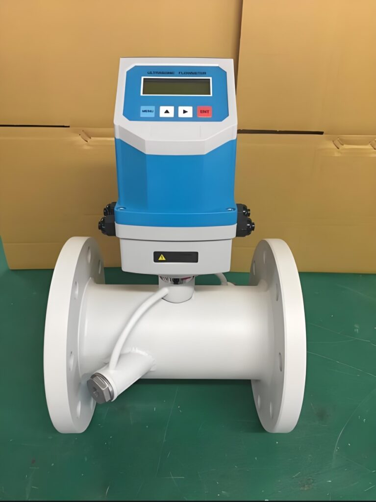
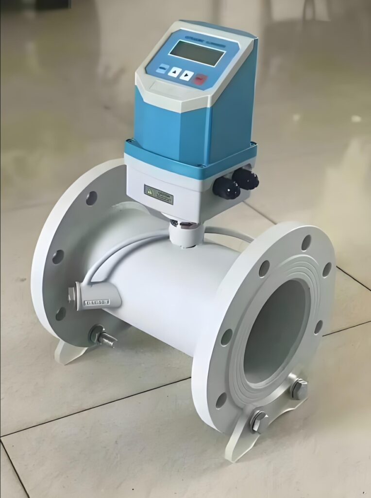
For complex disturbance conditions such as double elbows in different planes and partially closed regulating valves, the flow field distortion is more serious, and the upstream straight pipe requirement needs to reach 25D to 30D. In addition, multi-channel high-precision ultrasonic flowmeters used for fiscal metering have stricter standards, requiring upstream straight pipes of no less than 30D and downstream 10D to meet high-precision metering needs. Clamp-on and spool-piece ultrasonic flowmeters follow the same straight pipe standards, with no difference in basic installation conditions.
4. Field Problems and Optimization Solutions for Insufficient Straight Pipes
In actual industrial transformation projects, many old pipelines cannot meet the standard straight pipe length requirements due to limited installation space, resulting in persistent measurement errors. For such on-site problems, targeted optimization measures can be adopted to compensate for flow field defects. Installing flow straighteners is the most common and effective solution. Flow straighteners can quickly eliminate fluid swirling and turbulence, effectively reducing the straight pipe requirement to 5D upstream.
In addition, adjusting the installation position to avoid dense pipe fittings and selecting multi-beam ultrasonic flowmeters with strong flow field adaptability can also reduce the impact of insufficient straight pipes. For low-precision process monitoring scenarios, parameter offset calibration can be performed according to on-site comparison data to correct fixed errors caused by incomplete flow field development.
5. Conclusion
Straight pipe section requirement is a key standardized installation condition that determines the measurement accuracy of ultrasonic flowmeters. Sufficient upstream and downstream straight pipes can eliminate flow field distortion caused by pipeline accessories and provide a stable fluid environment for ultrasonic signal measurement. Different disturbance pipeline conditions and different precision application scenarios correspond to differentiated straight pipe length standards. For on-site situations where standard straight pipe conditions cannot be met due to space limitations, auxiliary optimization measures such as flow straighteners and algorithm calibration can be used for error compensation. Strictly implementing straight pipe installation specifications and adopting targeted optimization strategies for special working conditions can effectively avoid installation-induced measurement errors, stabilize flow data output, and ensure the long-term reliable operation of ultrasonic flowmeters in industrial pipeline measurement.
Scan the QR code to receive more detailed information.





