

Analysis and Explanation of Vortex Flow Meters
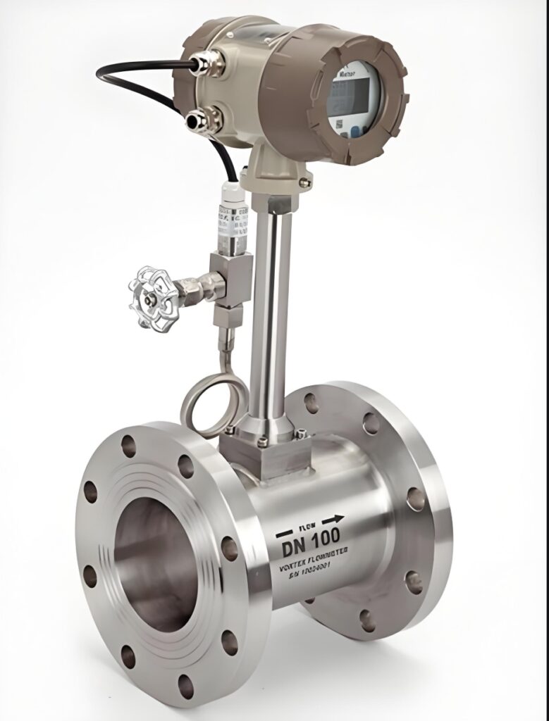
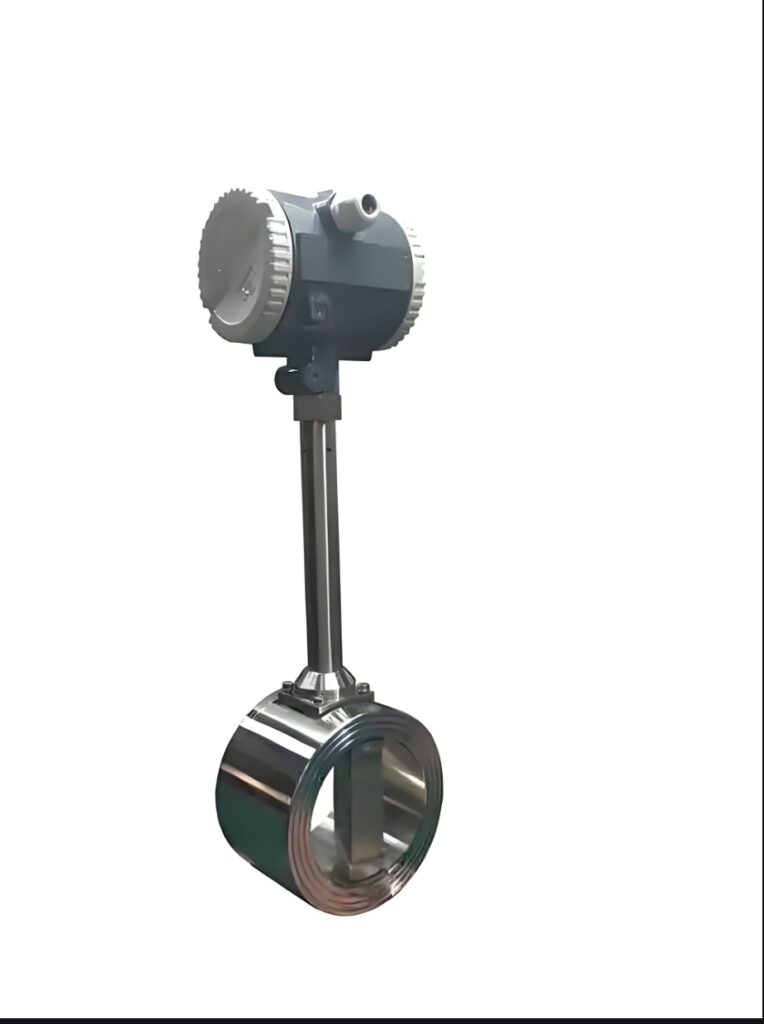
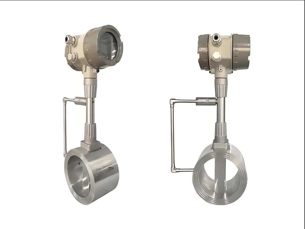
Vortex flow meters are velocity-type flow meters based on the Karman vortex street principle. They are suitable for measuring the volumetric/mass flow rate of gases, liquids, and steam. Their core advantages are no moving parts, low pressure loss, wide measuring range, and stable accuracy.
I. Working Principle
When fluid flows through a vortex generator (triangular prism/trapezoidal prism) within a pipe, regular vortices (Karman vortex street) are alternately generated on both sides.
Core Formula: f = St × v / d
Flow Rate Calculation: Q = K × f (K is the instrument coefficient, factory calibrated).
Detection Method: Piezoelectric/capacitive sensors capture the vortex frequency and convert it into an electrical signal output.
II. Structural Composition
Body: Flange/clamp-on type, connecting to the pipe, material includes 304/316L and carbon steel.
Vortex Generator: Triangular prism is the most common, generating a stable vortex street.
Sensor: Piezoelectric (mainstream, temperature resistance -40~+400℃), capacitive (good vibration resistance).
Signal Converter: Amplification, filtering, and calculation, outputting 4-20mA/pulse/RS485 signals.
III. Performance Characteristics
Advantages
High Reliability: No moving parts, maintenance-free, long service life.
Wide measuring range: Range ratio 1:10~1:20, accuracy ±1.0%~±1.5%.
Low pressure loss: Approximately 1/10 that of an orifice plate, resulting in significant energy savings.
High adaptability: Resistant to high temperatures (-40~+400℃) and high pressures, unaffected by density/viscosity (within a certain range).
Linear output: Frequency and flow rate are linear, facilitating metering and control.
Limitations
Low Flow Rate Restriction: Liquids ≥ 0.5 m/s, Gases/Steam ≥ 5 m/s; no vortex street below the lower limit.
General Vibration Resistance: Pipeline vibration easily causes signal fluctuations; vibration reduction is required.
Straight Pipe Section Requirements: ≥ 10D upstream, ≥ 5D downstream (D = pipe diameter); 15~20D is required if there are valves/elbows upstream.
Media Restrictions: Not suitable for media containing a large amount of solid particles, viscous media, or two-phase flow media.
IV. Typical Applications
Steam Metering: Boilers, thermal power plants, heating network systems (saturated/superheated steam).
Gas Measurement: Natural gas, compressed air, nitrogen, coal gas.
Liquid Metering: Water, heat transfer oil, solvents, acid and alkali solutions (clean, low viscosity).
Industry Scenarios: Chemical industry, thermal power, metallurgy, pharmaceuticals, food, municipal utilities.
V. Selection Guidelines
Media Type: High-temperature type for gas/steam; ordinary type for liquid; 316L material for corrosive media.
Diameter and Flow Rate:
· Liquid: Flow rate 1~5m/s (recommended).
· Gas: Flow rate 10~30m/s (recommended).
· Steam: Flow rate 20~50m/s (recommended).
Temperature and Pressure: Ordinary type ≤250℃, high-temperature type ≤400℃; Pressure rating PN16/PN25/PN40.
Output Signal: 4-20mA (analog), pulse (total), RS485/Modbus (communication).
Explosion-proof Rating: Exd II BT4/CT6 (chemical hazardous areas).
VI. Installation and Maintenance
Installation Requirements
Straight Pipe Sections: 10D before and 5D after, away from pumps, valves, and elbows (≥20D).
Direction: For horizontal installation, the sensor should be on the side of the pipe; for vertical installation, fluid should flow from bottom to top.
Vibration Prevention: Keep away from vibration sources and install vibration damping supports; avoid strong electromagnetic interference.
Maintenance Points
Regular Inspection: Clean the sensor, tighten wiring, and ensure there are no leaks.
Preventing Clogging: For media containing impurities, a filter (≤200 mesh) must be installed.
Parameter Calibration: Calibrate annually; temperature and pressure compensation must be matched to operating conditions.
VIII. Comparison with Other Flow Meters
* **Vortex Flow Meter vs. Orifice Plate:** Vortex flow meter has low pressure loss, wide flow range, and is maintenance-free; orifice plate flow meter has high pressure loss, requires regular replacement, and has high maintenance costs.
* **Vortex Flow Meter vs. Turbine Flow Meter:** Vortex flow meter has no moving parts and a long lifespan; turbine flow meter has bearing wear, requires regular lubrication, and has a short lifespan.
* **Vortex Flow Meter vs. Mass Flow Meter:** Vortex flow meter is inexpensive and easy to install; mass flow meter has high accuracy but is expensive and has extremely high installation requirements.
Vortex flow meters are general-purpose flow measurement instruments used in industrial fields. They are suitable for various media, including gases, ordinary liquids, saturated and superheated steam. With their advantages of no moving parts, high durability, wide adaptability to various operating conditions, and high cost-effectiveness, they are widely used in scenarios such as heating, petrochemicals, municipal water systems, energy consumption metering, and industrial process control. Unlike other metering instruments, the measurement principle of vortex flow meters is based on the vortex shedding frequency of fluids. This places extremely high demands on operating conditions, parameter matching, and environmental adaptability. Therefore, scientific and reasonable selection is the core prerequisite for accurate measurement and long-term stable operation of the instrument, directly affecting the safety, economy, and stability of industrial production.
Accurately selecting a vortex flowmeter that is well-suited to the operating conditions maximizes its advantages. With range matching, temperature and pressure resistance, media compatibility, and anti-interference performance fully aligned with the on-site conditions, the instrument can achieve long-term high-precision and high-stability measurements, effectively avoiding common problems such as flow drift, data fluctuations, and measurement lag. Simultaneously, proper selection can accurately avoid the inherent shortcomings of vortex flowmeters, such as pipeline vibration interference, low-velocity measurement failure, damage from high-temperature and high-pressure media, and corrosion from impurities, significantly reducing the probability of instrument failure and the frequency of equipment downtime for maintenance. This not only effectively extends the instrument’s service life and reduces equipment replacement, maintenance labor, and spare parts costs, but also provides continuous and reliable data support for production process adjustment, energy consumption statistics, material accounting, and trade settlement, ensuring the continuous and stable operation of the production line.
Conversely, blindly selecting models and mismatching parameters can lead to a series of serious production problems. Most issues with vortex flowmeters, such as inaccurate measurements, frequent malfunctions, and premature damage, stem from incorrect initial model selection. If the range is too large, measurement accuracy will drop significantly under low flow conditions; if the range is too small, measurement beyond the range will fail, and the probe may be overloaded and damaged. If the model is not matched to the characteristics of the medium, improper selection for corrosive, impurity-containing, or high-temperature and high-pressure media can cause probe wear, corrosion, and scaling, directly leading to measurement failure. Furthermore, ignoring environmental factors such as pipeline vibration, electromagnetic interference, and installation space can cause data fluctuations and measurement distortion, leading to deviations in process parameter adjustments, distorted production energy consumption statistics, and trade settlement disputes. This not only increases maintenance costs but, in severe cases, can also affect the stability of the production process, resulting in capacity loss and economic losses.
In summary, selecting a vortex flow meter is not simply a matter of matching equipment specifications, but a systematic selection process that considers media properties, operating parameters, site environment, and usage requirements. Accurate selection is crucial for ensuring instrument measurement accuracy, reducing maintenance costs, stabilizing production processes, and achieving refined energy consumption management. It plays an indispensable role in cost reduction and efficiency improvement, safe production, and compliant metering for industrial enterprises.
Please contact us promptly if needed.





