

Intelligent vortex flow meters can be installed vertically, but specific operating conditions and installation specifications must be met. The core is to avoid fluid disturbance and ensure stable vortex generation.
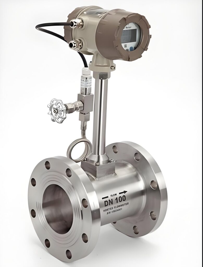
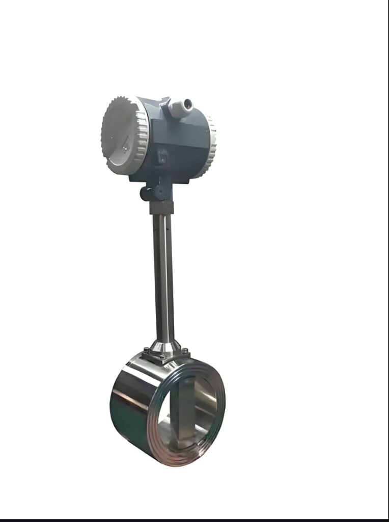
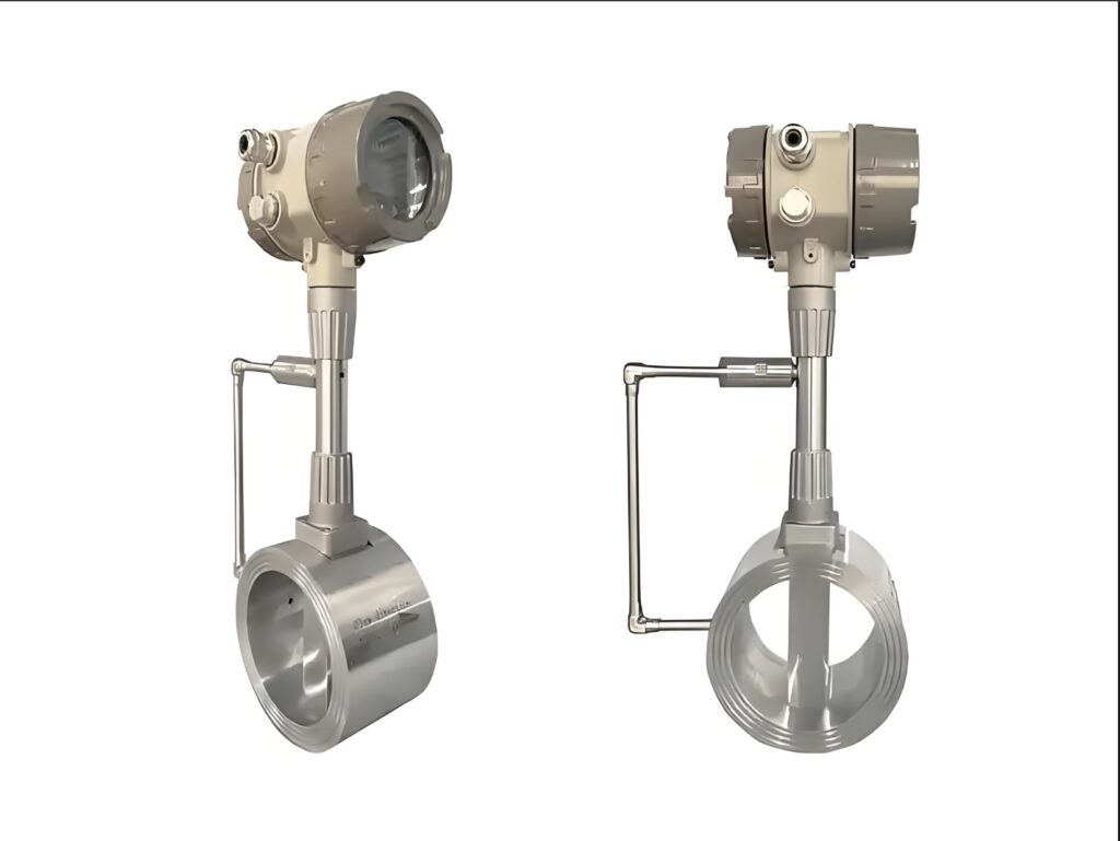
I. Core Prerequisites for Vertical Installation
1. **Fluid Flow Direction Requirements**:
**Bottom-up flow** is preferred (applicable to both liquids and steam) – This avoids air accumulation (in liquid conditions) or condensate deposition (in steam conditions) in the pipe, preventing interference from air bubbles/liquid accumulation on the vortex generator and ensuring measurement accuracy.
If top-down installation is the only option (due to pipe layout limitations), the following conditions must be met:
① The medium is **pure gas/superheated steam** (no condensate, no impurities);
② The pipe must be 100% full, and there must be no backflow caused by negative pressure downstream.
2. **Media Compatibility Limitations**:
– Suitable for: Gases, steam (saturated/superheated), clean liquids (no large amounts of impurities, no viscous deposits);
– Not recommended for: Liquids containing large amounts of air bubbles, media prone to crystallization/scaling, high-viscosity liquids (vertical installation can easily lead to uneven media distribution, affecting vortex generation).
II. Key Specifications for Vertical Installation
1. **Straight Pipe Section Requirements** (Consistent with horizontal installation, core guarantee):
Sufficient straight pipe sections must be reserved before and after the vortex generator to avoid flow field disturbances caused by valves, elbows, pumps, etc.:
– Upstream straight pipe section: ≥10 times the pipe inner diameter (DN);
– Downstream straight pipe section: ≥5 times the pipe inner diameter (DN);
If there are strong interfering components such as regulating valves or elbows (≤90°) upstream, the length needs to be extended to 15~20 times the DN.
2. **Installation Location and Environment**:
– Keep away from vibration sources (e.g., pumps, compressors): Vibration may falsely trigger vortex signals. A vibration-damping bracket must be installed, or the sensor must be kept at least 1 meter away from vibration sources.
– Special requirements for steam operation: When installed vertically, the sensor must be installed above the pipeline (flowing from bottom to top), and a condensate tank (for saturated steam) should be installed near the pipeline to prevent condensate from entering the sensor cavity.
– Liquid operation: Avoid installation on pipelines (as this can easily lead to air accumulation). If installation is necessary, an vent valve must be installed upstream of the sensor.
3. **Pipe and Sensor Matching**:
– Pipe Fullness: Must be 100% (For vertical installation, the pipe should fill naturally from bottom to top; for top to bottom, ensure there are no empty pipe sections downstream);
– Sensor Insertion Depth: As per manufacturer’s specifications (usually matched to the pipe’s inner diameter to ensure the vortex generator is located in the central flow zone of the pipe);
– Material Sealing: In high-temperature, high-pressure steam conditions, pressure-resistant flanges (PN ≥ operating pressure + 0.5 MPa) and high-temperature resistant seals (PTFE/metal gaskets) must be used to prevent leakage.
In summary, vertical installation of intelligent vortex flow meters is entirely feasible, but a bottom-up flow direction is **preferred** (suitable for most operating conditions such as steam and clean liquids). The key is to meet straight pipe section requirements and avoid fluid disturbance and media residue. If the operating condition is saturated steam (easily condensable water) or liquid containing a small amount of impurities, vertical installation (bottom-up) is more stable than horizontal installation. If the pipeline layout is limited and top-down installation is necessary, the purity of the medium must be strictly confirmed (no condensate, no air bubbles), otherwise it may lead to measurement errors or sensor damage.
Please contact us promptly if needed.





