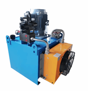
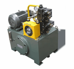
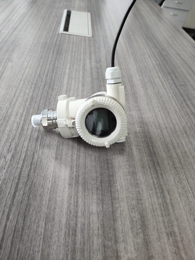
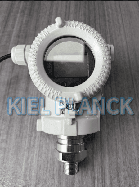
Many premature transmitter failures in hydraulic systems are not caused by poor product quality, but by overlooking key working condition parameters during specification. This article identifies seven critical parameters to evaluate before ordering pressure transmitters for hydraulic stations: pressure range & peak overload, medium compatibility, medium temperature, vibration and shock resistance, output signal type, process connection thread specification, and EMC protection. It explains how each parameter affects measurement stability and service life, and provides practical selection guidance for system integrators and maintenance engineers. Proper matching of these seven parameters can avoid signal drift, diaphragm damage and unexpected downtime, ensuring reliable pressure monitoring and closed-loop control for hydraulic power units.
Introduction
Hydraulic stations are widely used in machinery, metallurgy and injection molding industries. The pressure transmitter acts as the “eye” of the hydraulic control loop, feeding real-time pressure data to PLC and control valves. A common mistake in procurement is selecting transmitters merely based on nominal working pressure, ignoring the harsh dynamic characteristics of hydraulic circuits. Pressure spikes from pump startup, valve switching and load changes can easily damage a sensor sized only for steady pressure. Oil degradation and mechanical vibration also accelerate performance decay. Before finalizing any model, engineers must assess seven core working condition parameters, instead of only comparing accuracy on datasheets.
First, confirm the pressure range and peak overload capacity. Hydraulic systems have continuous working pressure plus transient pressure surges. The selected measuring range should reserve a safety margin, typically 1.5 times the normal operating pressure. Besides nominal range, proof pressure and burst pressure ratings are critical. If the transmitter cannot withstand repeated peak pressure, internal sensing elements will suffer permanent drift or rupture under pressure hammering.
Second, verify medium compatibility and wetted materials. Most hydraulic stations use mineral hydraulic oil, while some adopt water-glycol or synthetic ester fluids. The diaphragm and O-ring materials must match the hydraulic fluid. 17-4PH stainless steel diaphragms and FKM seals work well for standard mineral oil. Using incompatible elastomers will lead to seal swelling, oil leakage and medium intrusion into the sensor core.
Third, check medium and ambient temperature. Hydraulic oil temperature rises during continuous operation, sometimes reaching 80–100°C. High temperature worsens zero drift and weakens seal performance. The transmitter’s compensated temperature zone must cover the actual oil temperature range. Low ambient temperature in unheated workshops also causes oil viscosity change and signal deviation.
Fourth, evaluate vibration and shock resistance. Pumps and motors generate continuous mechanical vibration. Heavy shock occurs during equipment startup and emergency stop. Transmitters installed directly on pump outlets face the harshest vibration. Products with high anti-vibration ratings and internal damping structures prevent loose internal wiring and long-term zero shift.
Fifth, select the appropriate output signal. 4–20 mA current output remains the preferred choice for long-distance transmission and strong anti-interference in stationary hydraulic stations. Voltage signals like 0–10 V feature fast response for dynamic pressure testing. Digital signals such as IO-Link support remote parameter reading and diagnostics, suitable for intelligent hydraulic stations. The signal type must match the receiving module of the control system.
Sixth, confirm the process connection thread. Common threads include G, NPT and metric threads. Mismatched thread type or size leads to failed installation and oil leakage. Also check whether the mounting location requires a miniature or flush diaphragm structure to reduce pressure dead volume.
Seventh, examine EMC protection level. Hydraulic cabinets contain inverters and solenoid valves that produce strong electromagnetic interference. Without sufficient EMC compliance, the pressure signal will jump randomly, causing misjudgment of the control system and even unsafe load actions. Transmitters with IEC 61000 EMC protection perform steadily in noisy industrial environments.
In practice, many users prioritize accuracy over these seven parameters. High accuracy brings extra cost, but it cannot compensate for overload damage, chemical corrosion or vibration-induced drift. For hydraulic station monitoring, stability and overload resistance are often more important than ultra-high precision.
Conclusion
Selecting pressure transmitters for hydraulic stations requires systematic assessment of seven working condition parameters: pressure overload margin, medium compatibility, temperature range, vibration resistance, output signal, process thread and EMC capability. Hydraulic circuits are dynamic systems full of pressure spikes and mechanical disturbance; a transmitter that works well in static water measurement may fail quickly in hydraulic oil service. By checking these seven items before purchase, engineers can eliminate most on-site faults including signal fluctuation, seal failure and premature core damage. Matching the transmitter to real working conditions improves system safety, cuts maintenance costs and extends the service life of hydraulic power units. When preparing specifications, always record these seven parameters clearly in datasheet requirements rather than filling in only nominal pressure.
Scan the QR code to receive more detailed information.