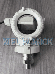
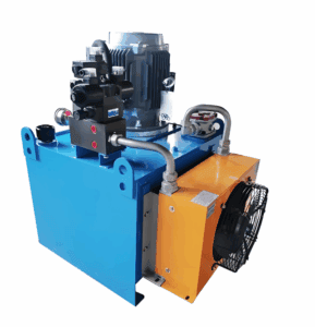
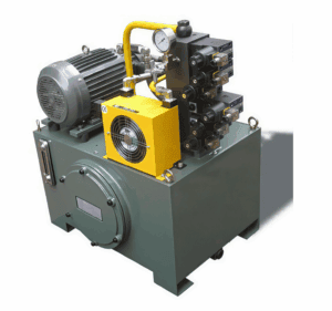
This common practice often leads to sensor drift, diaphragm damage, or insufficient measurement resolution caused by transient pressure spikes in hydraulic loops. Unlike static process pressure, hydraulic systems generate frequent pressure surges from valve switching, load impact and pump startup, which may far exceed the pump’s nominal rating. This article explains why copying pump rated pressure is risky, introduces the core principles for transmitter range calculation, and shares practical margin rules and field application cases. It also covers the difference between working pressure, peak surge pressure, proof pressure and burst pressure. Correct range selection balances measurement resolution and overload protection, avoiding premature sensor failure and unreliable closed-loop control for hydraulic power units.
Introduction
Hydraulic stations rely on pressure transmitters to provide real-time pressure feedback for PLC control, safety interlock and condition monitoring. When drafting technical specifications, one of the most frequent mistakes is taking the pump’s rated pressure as the transmitter range without further analysis. Pump rated pressure refers to the maximum continuous working pressure the pump can sustain in stable operation. It does not represent transient pressure peaks inside the pipeline. Pressure hammering and load shocks can create instantaneous pressure spikes 1.2 to 2 times higher than nominal pressure. If the transmitter range matches only the pump rating, these surges will stress the sensing element repeatedly. Over time, permanent zero drift or diaphragm rupture may occur.
To define a proper measuring range, engineers need to separate four pressure definitions clearly: normal operating pressure, maximum continuous pressure, transient peak pressure and pump rated pressure. The normal operating pressure is the stable pressure during routine production. The maximum continuous pressure is the upper limit maintained for long-duration operation. Transient peak pressure is short-duration pressure spikes, which happen instantly and last only milliseconds. The pump rated pressure is the design benchmark of the pump itself, not the actual pressure profile of the whole hydraulic circuit.
A general selection rule is to set the transmitter nominal range at 1.5 times the system’s maximum continuous working pressure, rather than the pump rated pressure. This margin accommodates routine pressure fluctuation. More importantly, the product’s proof pressure and burst pressure ratings must be higher than the expected transient peaks. Proof pressure is the pressure that the sensor can withstand without permanent performance shift, while burst pressure is the threshold of mechanical damage. Even if the nominal range is correctly sized, insufficient proof pressure will still cause sensor failure under repeated pressure shocks.
Meanwhile, measurement resolution cannot be ignored. Too large a range sacrifices resolution. For example, if the system normally runs at 100 bar with occasional peaks up to 150 bar, selecting a 400 bar transmitter will make small pressure changes hard to detect, weakening the precision of closed-loop control. Therefore, range selection is a trade-off between overload safety and measurement resolution.
Another critical factor is system safety settings. Most hydraulic stations are equipped with relief valves. The relief valve opening pressure must be considered in range calculation. When overload happens, the relief valve opens to limit pressure, but the response delay still creates brief pressure overshoot. Users often forget this overshoot value when referencing pump parameters. For safety-critical hydraulic equipment such as presses and lifting machinery, the pressure spike test data from the whole hydraulic loop should be used for range confirmation instead of pump datasheet values.
Installation position also affects pressure profile. Transmitters mounted directly at the pump outlet face stronger pressure pulsation and spikes than those installed after accumulators or damping assemblies. If the transmitter is placed at the pump port, a larger safety margin is required. Adding a pressure snubber can suppress sharp spikes, but a snubber is a supplementary solution and cannot replace correct range selection.
Many users argue that choosing a transmitter with the same range as the pump is simpler and saves cost. In reality, sensor replacement and unexpected downtime caused by overload damage bring far higher overall costs. High-quality transmitters with matched pressure rating deliver stable readings and longer service life.
Conclusion
Defining pressure transmitter range for hydraulic stations should never rely simply on copying the hydraulic pump’s rated pressure. The pump rated pressure only describes the pump’s continuous capacity and ignores transient pressure spikes, relief valve overshoot and pressure pulsation inside the hydraulic circuit. The recommended method is to analyze the system’s actual pressure profile, including normal working pressure, maximum continuous pressure and instantaneous peak pressure, then select a transmitter range with a reasonable safety margin. Engineers must also verify proof pressure and burst pressure specifications to resist pressure hammering. The goal is to balance overload protection and measurement resolution. Following this method reduces the risk of sensor drift and mechanical failure, improves the stability of hydraulic closed-loop control, and cuts long-term maintenance and replacement costs for hydraulic stations.
Scan the QR code to receive more detailed information.