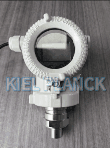
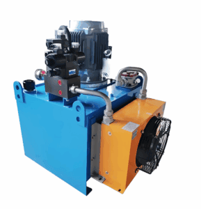
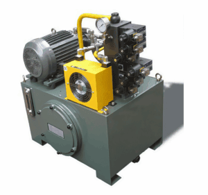
This article analyses common mounting position mistakes in hydraulic stations, including installation near pump outlets, poor pressure tapping orientation, excessive dead volume, and locations affected by gravity or flow turbulence. It explains how each error induces offset and fluctuation, and provides practical mounting guidelines. Correct placement eliminates unnecessary measurement deviation, ensures reliable pressure feedback for PLC control and safety interlocks, and avoids false alarms or misjudgements that may trigger abnormal actions of hydraulic actuators.
Introduction
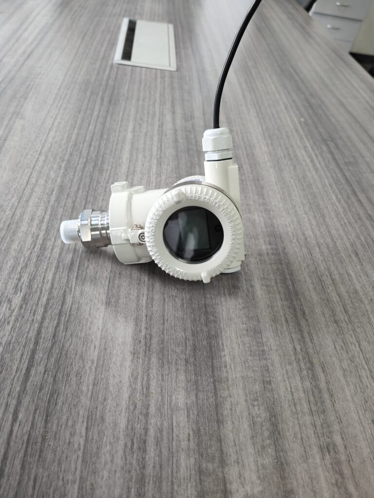
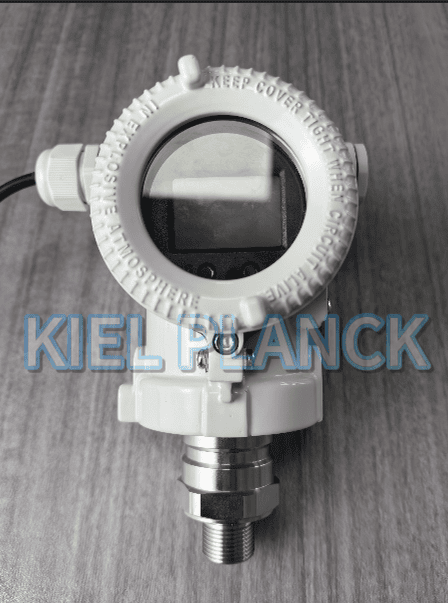
Pressure transmitters serve as key sensing devices for hydraulic power units, delivering real-time pressure signals for closed-loop control, overload protection and equipment status monitoring. Most purchasing and maintenance teams focus heavily on range selection, medium compatibility and vibration resistance, while treating mounting as a simple mechanical assembly task. They tend to install transmitters wherever threaded ports are available, without considering fluid pulsation, turbulence and hydrostatic pressure effects. In field practice, such careless installation can easily create measurement errors reaching 5% to 10%. This deviation is not caused by sensor damage or calibration failure, so routine zero adjustment cannot fully correct the error. Even high-precision transmitters will produce misleading readings if mounted at unsuitable points.
The first common error is installing transmitters directly at the pump outlet. Hydraulic pumps generate continuous pressure pulsation and instantaneous pressure spikes during operation. The fluid near the pump port has strong turbulence and pressure hammering. When mounted here without damping, the transmitter output will jump violently. The displayed value may be higher than the actual stable system pressure, creating a positive deviation. Although a pressure snubber can suppress sharp spikes, it cannot completely eliminate pulsation-induced offset. For stable pressure monitoring, the tapping point should be arranged downstream of the pump, after accumulators or straight pipe sections where fluid flow becomes steady.
Second mistake: incorrect pressure tapping orientation. For liquid hydraulic oil, the tapping hole direction directly affects trapped air. If the pressure port faces upward, air bubbles accumulate inside the impulse passage. Air is compressible and will absorb pressure changes, leading to slow response and low readings. In contrast, tapping ports pointing downward risk sediment blocking the small channel. The recommended orientation is side tapping, which prevents air accumulation and sediment deposition. Any trapped air inside the impulse tube is one of the top contributors to stable reading deviation.
Third issue comes from long or bent impulse lines with large dead volume. Some installers extend the pressure connection with extra pipe fittings to move the transmitter away from high-temperature components. Long, narrow impulse lines increase dead volume. When system pressure changes, oil compression inside the fitting delays pressure transmission and creates steady offset. Every unnecessary fitting and elbow adds potential error points. Keep the connection between the tapping point and transmitter as short and direct as possible. Flush diaphragm transmitters are preferred for locations prone to contamination.
Fourth factor is hydrostatic pressure caused by vertical height difference. When the transmitter is mounted far below or above the pressure tapping point, the weight of hydraulic oil column creates extra static pressure. This hydrostatic offset is a fixed value. If uncompensated, it adds a constant bias to readings. In low-pressure hydraulic circuits, this error can account for a large percentage of the measured value. Engineers need to calculate the oil column pressure and perform zero offset compensation after installation.
Another practical consideration is vibration. Mounting on vibrating structures such as valve blocks will cause signal drift over time. Select rigid mounting positions with lower mechanical vibration. Avoid locations exposed to direct heat sources that change oil viscosity and sensor temperature.
Many operators waste time repeatedly recalibrating transmitters to fix inaccurate readings. Recalibration cannot fix errors originating from poor mounting. Before replacing hardware, technicians should inspect the tapping position, air entrapment, impulse piping layout and height difference.
Conclusion
Mounting position selection is a critical step for hydraulic pressure measurement. A poorly chosen installation location can lead to reading deviations up to 10%, even when the pressure transmitter itself is calibrated and sized correctly. Pump outlet turbulence, trapped air from wrong tapping direction, excessive dead volume in impulse lines and hydrostatic pressure from vertical height differences are major sources of error. Transmitters should be installed at locations with stable flow, minimal vibration and suitable tapping orientation. Impulse piping must be kept short to reduce dead volume, and hydrostatic offset needs compensation where there is vertical elevation difference. By following proper mounting rules, engineers can remove installation-related measurement errors, obtain true system pressure data, stabilise hydraulic control performance and reduce troubleshooting workload in daily operation.
Scan the QR code to receive more detailed information.