

This paper systematically compares the working principles, core advantages, inherent limitations, and applicable operating conditions of the three types of flowmeters. It analyzes their adaptability to different fluid media, temperature and pressure environments, and industrial working conditions, and clarifies the selection criteria for practical engineering applications. The research aims to provide a clear technical reference for field engineers to choose optimal flow measurement equipment, effectively avoid measurement errors and equipment mismatch faults, and improve the overall efficiency and reliability of industrial flow monitoring systems.
1. Introduction
With the continuous upgrading of industrial automation, high-precision and stable flow measurement has become an essential guarantee for chemical production, water supply treatment, petroleum transportation, and power generation industries. Ultrasonic, electromagnetic, and turbine flowmeters occupy dominant positions in industrial flow measurement due to their respective technical advantages. Turbine flowmeters are typical mechanical measuring devices, while electromagnetic and ultrasonic flowmeters belong to non-mechanical intelligent measuring equipment. In actual engineering applications, unreasonable model selection often leads to reduced measurement accuracy, shortened service life, and even equipment failure. Therefore, comprehensively distinguishing the performance differences and applicable working conditions of the three flowmeters is of great significance for standardized industrial measurement and efficient process operation.
2. Working Principles Overview
The three flowmeters adopt completely different measurement principles. Ultrasonic flowmeters calculate fluid flow velocity based on the time difference of ultrasonic wave propagation in fluids, realizing non-contact or integrated non-intrusive measurement with no internal moving parts. Electromagnetic flowmeters work on Faraday’s electromagnetic induction law; they induce electromotive force through conductive fluid cutting magnetic field lines, and convert the signal into accurate flow data. Turbine flowmeters are mechanical measuring instruments, which drive the built-in turbine rotor to rotate by fluid impact, and calculate flow rate according to the proportional relationship between rotor speed and fluid velocity.
3. Pros, Cons and Applicable Operating Conditions
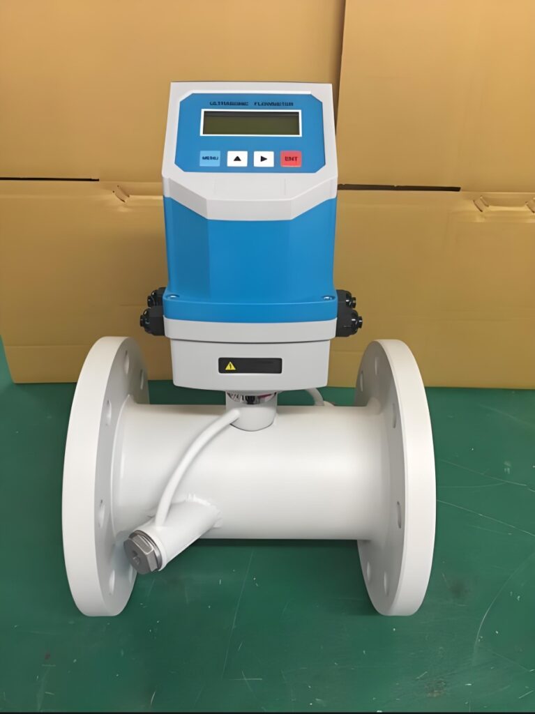
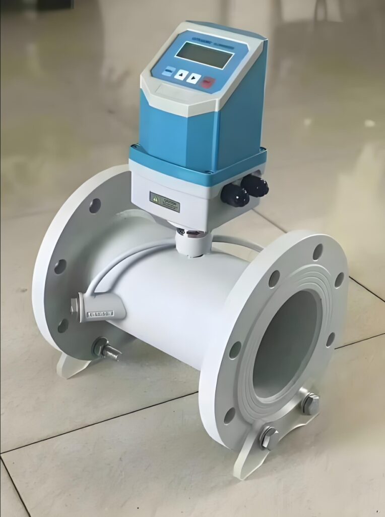
Ultrasonic flowmeters have prominent comprehensive advantages. Their core strengths include zero pressure loss, wide measuring range, and adaptability to liquid and gas media. They feature simple installation, no damage to fluid pipelines, and stable performance for high-pressure and high-temperature working conditions. However, they have obvious limitations: ultrasonic signals are susceptible to bubbles, suspended solids and electromagnetic interference, leading to data fluctuation. They are not suitable for turbid media with high impurity content. This type of flowmeter is widely used for measuring clean water, oil, and industrial gas, and is ideal for long-distance pipeline monitoring and high-pressure fluid metering scenarios.
Electromagnetic flowmeters excel in measuring conductive liquids. Their advantages include high measurement accuracy, strong anti-interference ability, and no restriction on fluid turbulence. They can adapt to corrosive, viscous and turbid conductive fluids such as sewage, slurry and chemical corrosive liquid, with stable operation and low maintenance cost. The biggest disadvantage is that they only work for conductive media, completely invalid for gas, oil and non-conductive liquids. Meanwhile, they are not suitable for ultra-high temperature and high-pressure extreme working conditions, and are vulnerable to pipeline stray current interference. They are mainly applied in sewage treatment, chemical industry, metallurgy and other conductive fluid measurement scenarios.
Turbine flowmeters have the highest measurement accuracy among the three, with fast response speed and stable data repeatability, which is suitable for high-precision fiscal metering. They feature simple structure and low manufacturing cost, making them cost-effective for conventional clean fluid measurement. Their fatal weakness is the mechanical moving rotor; long-term fluid impact causes rotor wear, leading to accuracy attenuation and short service life. In addition, they are prone to blockage by impurities and cannot adapt to high-viscosity fluids. They are mostly used for precise measurement of clean oil, purified water and low-viscosity industrial liquids in stable working conditions.
4. Industrial Selection Guidelines
In practical engineering selection, medium characteristics are the primary judgment basis. For non-conductive clean fluids and gas, ultrasonic flowmeters are the priority. For conductive turbid, corrosive and slurry fluids, electromagnetic flowmeters are the best choice. For high-precision metering of clean low-viscosity fluids with stable working conditions, turbine flowmeters can be selected to balance accuracy and cost. Meanwhile, working condition parameters such as pipeline pressure, fluid temperature and on-site electromagnetic environment should be comprehensively considered to avoid performance limitations of different flowmeters.
5. Conclusion
Ultrasonic, electromagnetic, and turbine flowmeters have their own unique strengths and limitations with distinct applicable operating conditions. Ultrasonic flowmeters feature wide adaptability and zero pressure loss but are sensitive to medium impurities. Electromagnetic flowmeters perform well in conductive complex fluids but have strict medium conductivity limitations. Turbine flowmeters achieve ultra-high measurement accuracy but suffer from mechanical wear and poor anti-pollution ability. In industrial applications, engineers must combine actual fluid characteristics, working condition parameters and measurement accuracy requirements for targeted selection. Reasonable matching of flowmeter types and working conditions can effectively ensure long-term stable and accurate flow measurement, reduce equipment maintenance costs, and provide reliable data support for industrial production and energy metering.
Scan the QR code to receive more detailed information.





