

This paper systematically elaborates on the core selection specifications and standardized installation criteria of spool-piece ultrasonic flowmeters. It analyzes key selection parameters including measurement accuracy, flow velocity range, temperature and pressure resistance, and media applicability, and summarizes critical installation requirements such as straight pipe section length, installation position, environmental conditions, and electrical wiring standards. Additionally, it clarifies common installation errors and calibration precautions in industrial scenarios. The study aims to provide standardized technical guidelines for the reasonable selection and compliant installation of spool-piece ultrasonic flowmeters, effectively improving the accuracy and long-term operational stability of industrial flow measurement systems.
1. Introduction
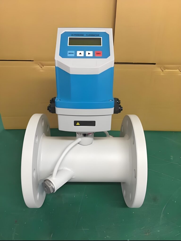
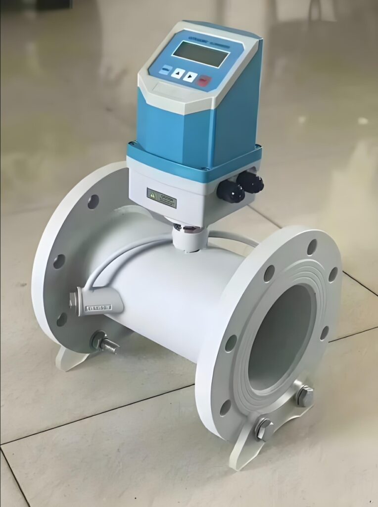
Flow measurement is a core link in industrial process control, energy metering, and fluid pipeline monitoring. Spool-piece ultrasonic flowmeters have gradually become the preferred equipment for high-precision flow measurement in petroleum, chemical, water supply, and power industries. Different from external clamp-on products, spool-piece ultrasonic flowmeters adopt an integrated pipeline design, with ultrasonic transducers pre-installed on the factory-calibrated spool piece. This structure avoids measurement errors caused by transducer displacement and poor pipeline fitting, delivering a measurement accuracy of ±0.15% to ±0.5% for standard industrial applications. However, improper model selection and non-standard installation will directly lead to increased measurement deviation, signal attenuation, and even equipment failure. Therefore, strictly following professional specifications for selection and installation is essential to give full play to the performance advantages of the equipment.
2. Core Selection Specifications
Scientific model selection is the premise of stable operation of spool-piece ultrasonic flowmeters, which needs to be matched with actual working conditions and process parameters comprehensively. First, accuracy grade selection should be based on application scenarios. For fiscal metering and custody transfer scenarios requiring high precision, flowmeters with an accuracy better than ±0.5% must be selected, while general process monitoring can adopt standard accuracy products to control costs.
Second, flow velocity and pipeline matching are crucial. The conventional measurable flow velocity range of industrial spool-piece flowmeters is 0 to 12 m/s, and high-precision models can reach 30 m/s. Users need to confirm the actual flow velocity range of the pipeline to avoid long-term operation beyond the measuring range. Meanwhile, the spool piece diameter must be consistent with the on-site pipeline diameter to prevent fluid turbulence caused by pipe diameter mismatch, which affects measurement accuracy.
In addition, environmental and media adaptability specifications cannot be ignored. Standard products are suitable for fluid temperatures from 0°C to 35°C, while high-temperature and low-temperature customized models are required for extreme working conditions. The equipment pressure resistance grade shall match the pipeline operating pressure, and explosion-proof models must be selected for hazardous locations with flammable and explosive media. Moreover, the measured medium should be clean liquid or gas with low impurity content; excessive suspended solids or bubbles will interfere with ultrasonic signal transmission and reduce measurement stability.
3. Standard Installation Specifications
Installation standardization directly determines the final measurement effect of the flowmeter, with straight pipe section requirements as the core installation index. Industrial unified specifications stipulate that the upstream straight pipe length of the spool-piece flowmeter shall not be less than 10 times the pipe diameter (10D), and the downstream straight pipe length shall not be less than 5 times the pipe diameter (5D). This requirement ensures fully developed fluid flow and eliminates turbulence and swirling flow interference caused by elbows, valves, and pipe reducers.
For installation position selection, the flowmeter should be installed on horizontal or vertical stable pipe sections. When installed horizontally, the transducer mounting surface should be kept horizontal to prevent gas accumulation or sediment deposition from covering the detection area. It is forbidden to install the equipment at the pump outlet, pipeline bending sections, and positions with severe fluid pulsation to avoid signal fluctuation. Meanwhile, the installation site must be free from severe vibration, strong electromagnetic interference, and long-term moisture immersion, and sufficient maintenance space should be reserved.
In terms of electrical installation, signal cables need to adopt shielded wires, with single-point grounding at the master station side to avoid electromagnetic noise interference. Both ends of the communication cable shall be equipped with 120Ω matching resistors to ensure stable signal transmission. After installation, pipeline pressure tightness test and equipment zero-point calibration must be carried out to eliminate installation stress and pipeline residual stress errors.
4. Installation Commissioning and Error Prevention
After installation, standardized commissioning is required to verify equipment performance. Firstly, check the firmness of spool piece connection and the sealing of flange joints to prevent fluid leakage. Secondly, observe the ultrasonic signal strength through the transmitter; stable signal intensity indicates qualified installation, while weak or fluctuating signals mean installation deviation or medium interference. In addition, long-term operation monitoring specifications require regular inspection of transducer working status and pipeline cleanliness to avoid measurement drift caused by medium scaling and impurity adhesion.
Common installation errors include insufficient straight pipe sections, incorrect installation angle, and ungrounded shielded cables. These problems will cause systematic measurement errors and even equipment failure. Therefore, the whole process of installation must be implemented in accordance with technical specifications, and professional personnel shall complete construction and commissioning.
5. Conclusion
Spool-piece ultrasonic flowmeters rely on integrated structural advantages to achieve high-precision and low-loss fluid measurement, and their application effect is completely dependent on standardized selection and installation. Scientific model selection based on working condition parameters such as measurement accuracy, flow velocity, temperature and pressure is the foundation of stable equipment operation. Strict compliance with straight pipe section standards, installation position requirements, and electrical wiring specifications can effectively avoid measurement errors caused by non-standard construction. In industrial practical applications, personnel should always take technical specifications as the guideline, standardize the whole process of selection, installation and commissioning, and regularly maintain the equipment. This can maximize the measurement performance of spool-piece ultrasonic flowmeters, provide accurate and reliable data support for industrial production and energy metering, and improve the overall operational efficiency of fluid pipeline systems.
Scan the QR code to receive more detailed information.





