

This paper systematically introduces the common communication modes of intelligent vortex flow meters, standard wiring specifications, step-by-step operation procedures, safety precautions and common wiring fault troubleshooting. The purpose is to provide standardized technical guidance for field construction personnel, ensure the reliability of instrument communication links, and guarantee the long-term stable operation of industrial flow measurement and control systems.
1. Introduction
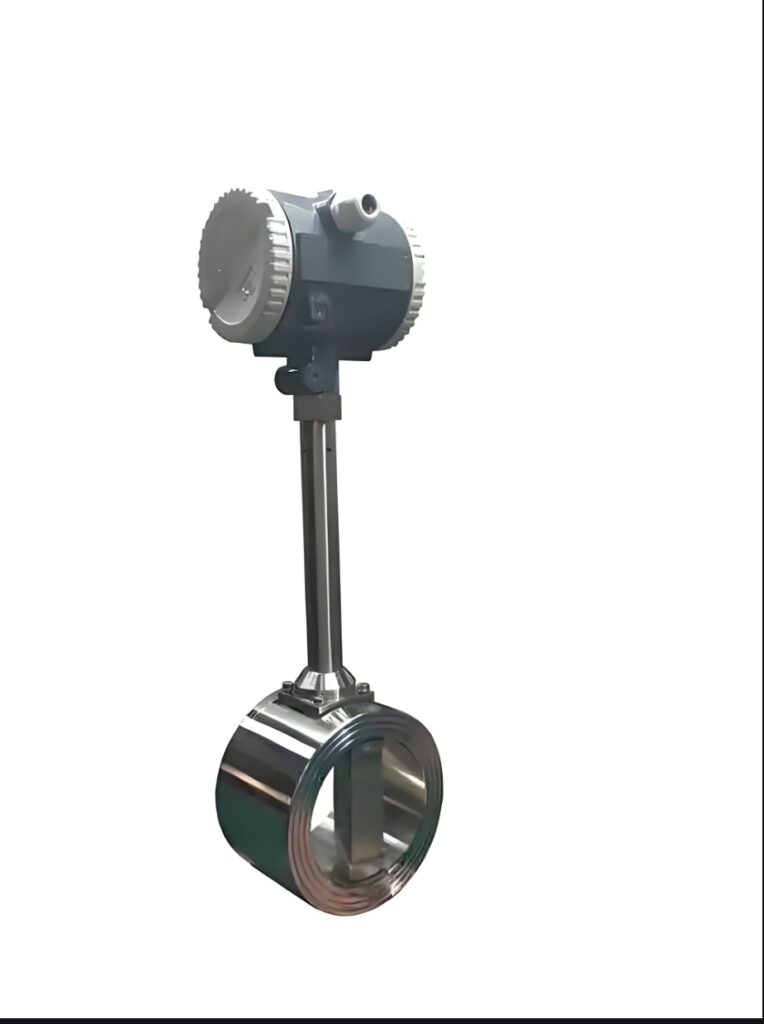
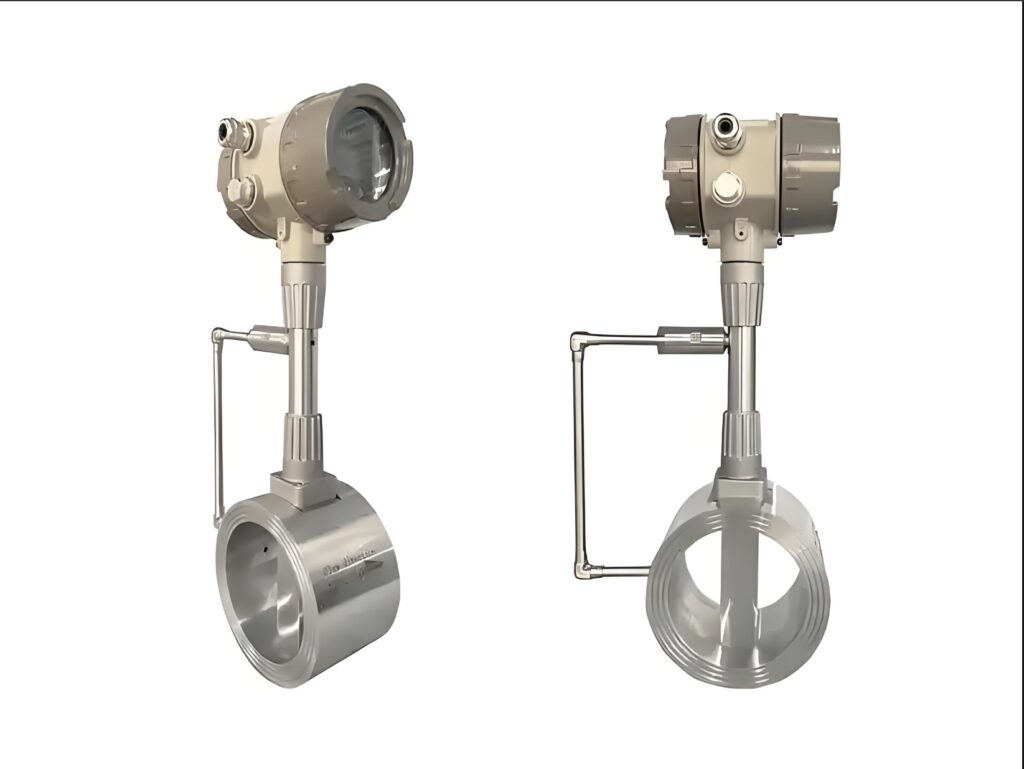
Intelligent vortex flow meters are upgraded industrial measuring devices equipped with microprocessor units and digital communication interfaces. In addition to realizing accurate flow measurement of gas, liquid and steam, they support remote data transmission through 4-20 mA analog signal, RS485 Modbus and HART communication protocols. In industrial automation systems, wiring quality directly determines the accuracy and stability of data interaction between field instruments and PLC or DCS control systems. Irregular wiring construction, incorrect line sequence connection and unstandardized grounding are common on-site problems, which lead to communication interruption, data jumping and low system stability. Therefore, mastering standardized communication wiring methods and specification requirements is essential for engineering installation, commissioning and daily maintenance of intelligent vortex street instruments.
2. Common Communication Modes and Wiring Principles
Intelligent vortex street instruments mainly adopt three mainstream communication modes, each with independent wiring specifications. The first is 4-20 mA analog signal transmission, which is the most widely used conventional mode. It transmits instantaneous flow values through current signals and features strong anti-interference and simple wiring. The second is RS485 Modbus digital communication, which supports multi-point networking, remote parameter reading and instrument modification, suitable for centralized monitoring of multiple flow meters. The third is HART communication, which realizes digital signal superposition on the basis of analog current signals, compatible with both traditional analog systems and intelligent digital management.
The core wiring principle is to ensure signal independence, shielding integrity and safe grounding. Analog signals and digital communication signals need isolated wiring to avoid crosstalk. All communication cables must use shielded twisted-pair wires to resist on-site electromagnetic interference from high-power equipment such as motors and frequency converters, ensuring the continuity and stability of transmission signals.
3. Standard Step-by-Step Wiring Procedures
The wiring construction of intelligent vortex street instruments follows the standardized process of preparation, inspection, wiring and verification. First, complete pre-construction preparation, including power-off operation, cable selection and appearance inspection. Select matched shielded cables according to communication types, check that the cable insulation layer is intact without damage, and confirm the instrument communication interface parameters are consistent with the control system settings.
Second, conduct terminal wiring in strict accordance with the instrument wiring diagram. For 4-20 mA signals, connect the positive and negative poles of the current loop correctly to avoid reverse connection; for RS485 communication, distinguish A/B signal lines strictly to prevent reversed line sequence leading to communication failure. Fix the wiring terminals firmly to avoid virtual connection and poor contact. Third, complete shielding layer grounding processing. The shielded layer of the communication cable must be grounded at the control system end in a single-point manner to eliminate circulating current interference caused by multi-point grounding.
Finally, perform power-on test and communication debugging. After wiring is completed, turn on the power supply, observe the instrument display status, check whether the control system can normally receive real-time flow data, and verify the accuracy of remote parameter reading and writing to complete the whole wiring process.
4. Key Wiring Specifications and Safety Precautions
On-site wiring construction needs to strictly abide by industry specifications to avoid hidden dangers. First, communication cables must be laid separately from high-voltage power cables, with a spacing of more than 30 centimeters to prevent electromagnetic signal interference. Cable laying should avoid sharp bends and tensile extrusion to protect internal core wires and shielding layers. Second, multi-point grounding is strictly prohibited for shielded cables, which is the main cause of data fluctuation and communication instability. Third, in flammable and explosive petrochemical environments, wiring must comply with explosion-proof standards, with sealed cable joints and explosion-proof wiring boxes to ensure production safety.
In addition, long-distance communication wiring needs to control cable length within the effective transmission range. Excessively long cables will cause signal attenuation and delay. After wiring, standard cable marking and arrangement should be carried out to facilitate subsequent daily maintenance and fault inspection.
5. Common Wiring Faults and Troubleshooting
Common communication faults include no signal transmission, unstable data and intermittent communication interruption. Most faults are caused by non-standard wiring. No signal is usually caused by wrong line sequence, loose terminals or power supply failure. Unstable data is mainly due to ungrounded shielding layers, multi-point grounding or mixed laying of signal cables and power cables. Intermittent interruption generally results from virtual connection of terminals and damaged cable core wires.
Corresponding troubleshooting methods include checking line sequence consistency, re-fastening wiring terminals, reprocessing shielding grounding, and rearranging cable paths. After troubleshooting, secondary communication debugging and signal stability testing are required to ensure the communication link works continuously and stably.
6. Conclusion
Standard communication wiring is the basic guarantee for the normal operation and stable data transmission of intelligent vortex street instruments. Different communication modes have independent wiring specifications and technical requirements, and standardized construction, correct grounding and reasonable cable layout can effectively avoid signal interference and communication faults. Strict implementation of wiring operation procedures and safety precautions in field engineering can significantly improve the reliability of instrument remote communication and the stability of industrial automatic control systems. Standardized wiring technology not only reduces equipment failure rate and maintenance cost, but also provides solid technical support for the intelligent and digital upgrading of industrial flow measurement.
Scan the QR code to receive more detailed information.





