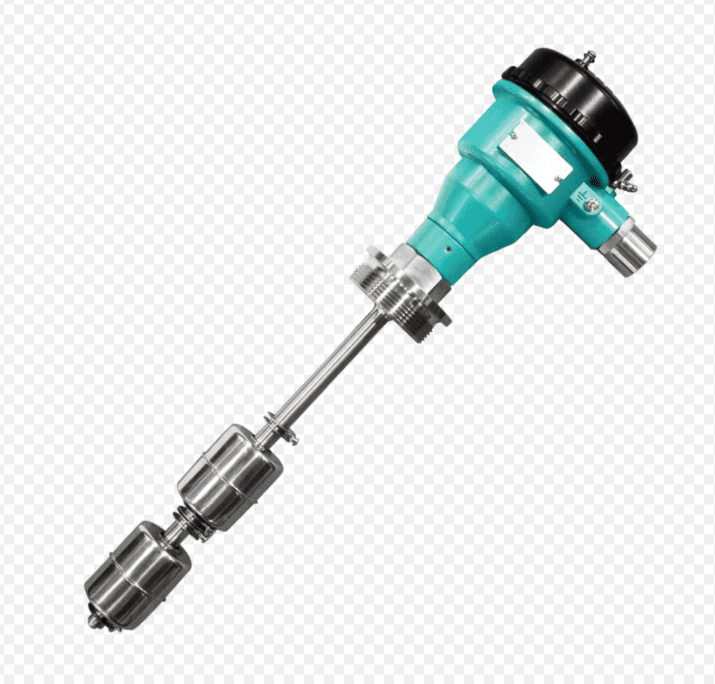
What is the contact capacity of a side-mounted float level switch? - Kiel Planck
  • Home
        • New Product

          What is the contact capacity of a side-mounted float level switch? - Kiel Planck

          There is a solution for every application. Let’s work together to find the right solution for you.

          Your benefits

          We use our experience to move your project forward.

          PHONE: 400-8868-261

          E-mail: info@kielplanckprc.com / kielplanck@outlook.com

  • Application
  • Service
  • Brand
  • Blog
  • Contact Us

What is the contact capacity of a side-mounted float level switch?

What is the contact capacity of a side-mounted float level switch?

Side-mounted float level switch contact capacity (divided into three types: micro-motion mechanical, reed switch, and explosion-proof intrinsically safe, industrial standard)
Side-mounted switches are available in two mechanisms: lever magnetic micro-switch (UQK side-mounted mechanical) and built-in reed magnetic switch. The contact capacity differs significantly, and all are SPDT single-pole double-throw (1 open, 1 closed) contacts.

I. Micro-switch type (lever side-mounted, commonly used in industry, high power)
AC: 250VAC, 5A (resistive load 1250VA), standard configuration; heavy-duty customization up to 250VAC/10A.

DC: 125VDC/0.4A, 220VDC/0.3A, 24VDC maximum 5A (small DC load).

Applications: Direct start/stop of water pumps, solenoid valves, water treatment, local control of tanks.

II. Reed Switch Type (Miniature Side-Mounted, Passive Signal Output, Small Capacity) Standard Model: AC220V/0.5A (50VA); DC24V/0.5A (12W), Maximum Capacity: AC240V/1A, DC200V/0.7A (50W).

Miniature Corrosion-Resistant PP Side-Mounted

Low Capacity: AC10VA, DC10W, AC≤0.3A, for PLC and indicator light signal circuits only.

Applications: Remote transmission of DI signals, alarm indicator lights. Directly powering high-power loads is strictly prohibited; intermediate relays must be added for capacity expansion.

III. Explosion-Proof/Intrinsically Safe Side-Mounted Dedicated Capacities

Explosion-Proof Exd Type: Same parameters as conventional micro-motion/reed switches, available in AC250V/5A and AC50VA specifications. Temperature limits on the casing must prevent overloading.

Intrinsically Safe Exia (Chemical Explosion-Proof Instruments): DC24V only, ≤0.5A, ≤10W. Do not connect to 220V high-voltage power.

IV. Selection and Usage Guidelines

**Resistive Loads (Indicator Lights, Intermediate Relays):** Select according to nominal capacity;
**Inductive Loads (Coils, Water Pumps):** Derating by 30%;
**Reed contacts should be used in conjunction with intermediate relays for high-power applications to avoid arcing and contact erosion;
**Low-Crystal/Liquid Nitrogen Applications:** Select low-capacity reed contacts: DC24V/0.3A is optimal.

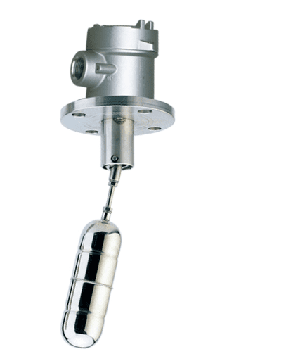
What is the contact capacity of a side-mounted float level switch? - Kiel Planck

Scan the QR code to receive more detailed information.

What is the contact capacity of a side-mounted float level switch? - Kiel Planck

Share:

More Posts

How to Measure Inlet Gas Flow of Water Electrolysis Hydrogen Production Units? - Kiel Planck

How to Measure Inlet Gas Flow of Water Electrolysis Hydrogen Production Units?

Stable and accurate inlet gas flow monitoring is the core prerequisite for efficient and safe operation of water electrolysis hydrogen production equipment. The inlet raw gas of electrolytic hydrogen production features low viscosity, high cleanliness and mild operating pressure, putting forward specific requirements for flow measurement instruments. As a high-precision, fast-response speed-type measuring device, gas turbine flow meters are gradually applied in hydrogen production inlet pipeline monitoring.

Do Not Use Turbine Flow Meters for These Media: List of Six Unfavorable Working Conditions - Kiel Planck

Do Not Use Turbine Flow Meters for These Media: List of Six Unfavorable Working Conditions

Turbine flow meters are widely recognized for their high accuracy, excellent repeatability and fast dynamic response, making them mainstream equipment for industrial fluid custody transfer and precise process metering. However, their core rotating impeller and precision bearing structure determines strict limitations in medium adaptability. Blind application in inappropriate working conditions easily causes bearing abrasion, impeller deformation, signal failure and rapid performance attenuation

How to Solve Vortex Flow Meter Probe Fouling and Corrosion - Kiel Planck

How to Solve Vortex Flow Meter Probe Fouling and Corrosion

Vortex flow meters rely on bluff body probes to generate regular Karman vortex streets, making probe surface condition the key to stable and accurate flow measurement. In industrial scenarios such as chemical production, sewage treatment, steam pipelines and brine transportation, probes are prone to scaling, adhesive fouling and electrochemical corrosion after long-term operation. Damaged probe surfaces disrupt vortex generation, cause signal jitter, measurement deviation and even meter failure.

Vortex Flow Meters Need No Temperature and Pressure Compensation” - Kiel Planck

Vortex Flow Meters Need No Temperature and Pressure Compensation”

A widespread misconception in the industrial instrumentation industry claims that vortex flow meters operate accurately without temperature and pressure compensation. This simplified but misleading statement has misled numerous purchasers and engineering teams into improper configuration, resulting in severe measurement deviations, inaccurate energy statistics and unqualified custody transfer data.

Send Us A Message

captcha
Reload

Bitte geben Sie die im CAPTCHA angezeigten Zeichen ein, um sicherzustellen, dass Sie ein Mensch sind.

Email
Email: info@kielplanckprc.com
WhatsApp
WhatsApp Me