Basic knowledge of cooling water flow switch - Kiel Planck
  • Home
        • New Product

          Basic knowledge of cooling water flow switch - Kiel Planck

          There is a solution for every application. Let’s work together to find the right solution for you.

          Your benefits

          We use our experience to move your project forward.

          PHONE: 400-8868-261

          E-mail: info@kielplanckprc.com / kielplanck@outlook.com

  • Application
  • Service
  • Brand
  • Blog
  • Contact Us

Basic knowledge of cooling water flow switch

Basic knowledge of cooling water flow switch

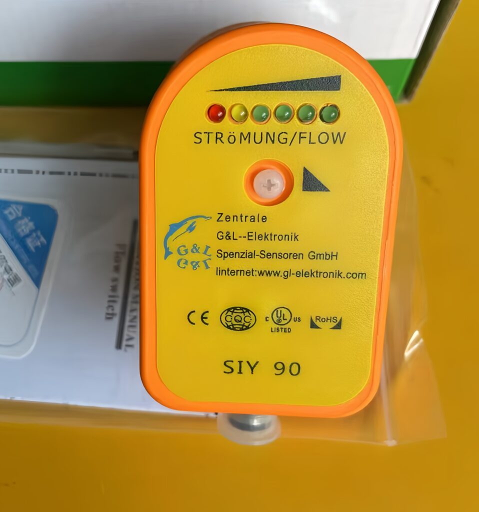
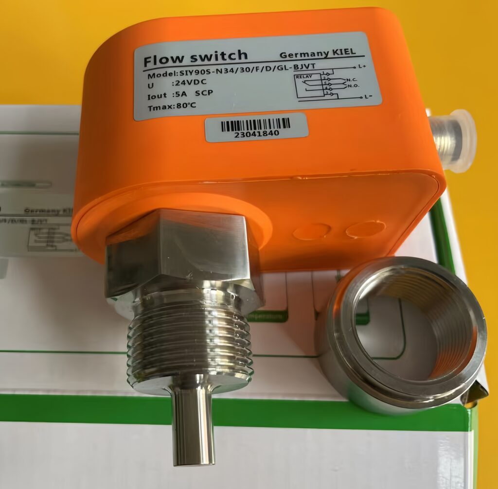
A cooling water flow switch is a safety control device used to monitor the flow status of cooling water. It will issue an alarm signal to protect the equipment when the water flow stops or falls below the set value.

Basic knowledge of cooling water flow switch - Kiel Planck

The main working principles include:

Mechanical (baffle type): When water flows in the pipe, the water flow pushes a metal plate or baffle to deflect, activating the circuit and sending a water flow signal.

Thermal type: Utilizes the principle of temperature change of the probe, detecting flow rate by measuring the temperature difference between a heating sensor and a thermal sensor.

Differential pressure type: Measures the pressure drop across valves, orifices, etc., and obtains accurate flow rate based on the pressure drop and flow rate curve.

Main functions:

The core functions of the cooling water flow switch include:

Real-time monitoring: Monitors the flow status of cooling water to ensure unit operation. Temperature within a reasonable range

Alarm Protection: Issues an alarm signal when water flow stops or becomes abnormal, notifying the central control room to take action.

Equipment Interlocking: Interlocks with pumps, valves, and other equipment for control, preventing equipment from running dry or overloaded.

Typical Applications

Widely used in:

Industrial Equipment: Water-cooled welding machines, laser equipment cooling systems, vacuum coating machines, electric furnaces, polycrystalline silicon ingot furnaces, etc.

HVAC Systems: Water flow control for air-cooled or water-cooled chillers.

Building Automation: Monitoring of cooling water and chilled water circuits in air conditioning systems.

Technical Parameters

Common Technical Indicators:

Start-up flow rate: Typically triggers at flow rates above 1.0 liters per minute.

Response time: Typically 2 seconds.

Temperature range: -25℃ to 80℃.

Pressure rating: 10MPa6.

Installation points:

Installation precautions:

Should be installed on a straight pipe with at least 5 times the pipe diameter on both sides.

Keep the arrow on the flow switch housing aligned with the direction of fluid flow in the pipe.

Avoid installation at pipe bends or locations with significant water flow disturbance.

Cannot be subjected to water hammer; a flow throttle should be installed for protection.

Add me as a friend to learn more.

Basic knowledge of cooling water flow switch - Kiel Planck

Share:

More Posts

How to Measure Inlet Gas Flow of Water Electrolysis Hydrogen Production Units? - Kiel Planck

How to Measure Inlet Gas Flow of Water Electrolysis Hydrogen Production Units?

Stable and accurate inlet gas flow monitoring is the core prerequisite for efficient and safe operation of water electrolysis hydrogen production equipment. The inlet raw gas of electrolytic hydrogen production features low viscosity, high cleanliness and mild operating pressure, putting forward specific requirements for flow measurement instruments. As a high-precision, fast-response speed-type measuring device, gas turbine flow meters are gradually applied in hydrogen production inlet pipeline monitoring.

Do Not Use Turbine Flow Meters for These Media: List of Six Unfavorable Working Conditions - Kiel Planck

Do Not Use Turbine Flow Meters for These Media: List of Six Unfavorable Working Conditions

Turbine flow meters are widely recognized for their high accuracy, excellent repeatability and fast dynamic response, making them mainstream equipment for industrial fluid custody transfer and precise process metering. However, their core rotating impeller and precision bearing structure determines strict limitations in medium adaptability. Blind application in inappropriate working conditions easily causes bearing abrasion, impeller deformation, signal failure and rapid performance attenuation

How to Solve Vortex Flow Meter Probe Fouling and Corrosion - Kiel Planck

How to Solve Vortex Flow Meter Probe Fouling and Corrosion

Vortex flow meters rely on bluff body probes to generate regular Karman vortex streets, making probe surface condition the key to stable and accurate flow measurement. In industrial scenarios such as chemical production, sewage treatment, steam pipelines and brine transportation, probes are prone to scaling, adhesive fouling and electrochemical corrosion after long-term operation. Damaged probe surfaces disrupt vortex generation, cause signal jitter, measurement deviation and even meter failure.

Vortex Flow Meters Need No Temperature and Pressure Compensation” - Kiel Planck

Vortex Flow Meters Need No Temperature and Pressure Compensation”

A widespread misconception in the industrial instrumentation industry claims that vortex flow meters operate accurately without temperature and pressure compensation. This simplified but misleading statement has misled numerous purchasers and engineering teams into improper configuration, resulting in severe measurement deviations, inaccurate energy statistics and unqualified custody transfer data.

Send Us A Message

captcha
Reload

Bitte geben Sie die im CAPTCHA angezeigten Zeichen ein, um sicherzustellen, dass Sie ein Mensch sind.

Email
Email: info@kielplanckprc.com
WhatsApp
WhatsApp Me