

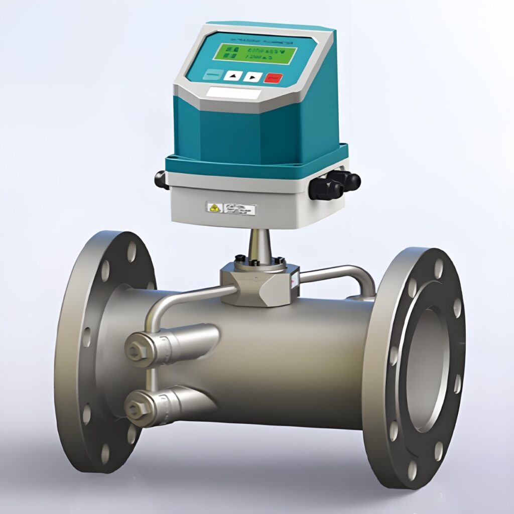
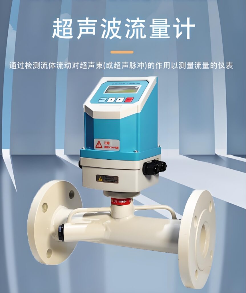
An external clamp-on ultrasonic flow meter is an instrument that measures fluid flow rate non-invasively by directly mounting the sensor on the outer wall of the pipe and using ultrasonic technology. It has the advantages of easy installation, no pressure loss, and a wide range of applicable pipe diameters. It is especially suitable for occasions where it is inconvenient to stop production or where pipe openings are not allowed.
I. Working Principle
Clamp-on ultrasonic flow meters primarily operate based on two principles:
1. Time Difference Method (Propagation Time Difference Method)
This is the most commonly used measurement principle. When ultrasonic waves propagate in a fluid, the propagation speed of the sound wave in the downstream direction is greater than that in the upstream direction. The flow meter calculates the average flow velocity of the fluid by measuring the time difference of ultrasonic wave propagation in the downstream and upstream directions, and thus obtains the flow rate. Its basic formula is:
v=L²cosθ⋅Δt t1t2v=2cosθL⋅t1t2Δt
Where:
vv: Average fluid velocity
L: Propagation distance of the ultrasonic wave in the fluid
θθ: Angle between the sound beam and the pipe axis
ΔtΔt: Propagation time difference between upstream and downstream directions
t1,t2t1,t2: Propagation time in the downstream and upstream directions
2. Doppler Method
Suitable for fluids containing bubbles or solid particles. When an ultrasonic wave encounters a reflective object (bubble or particle) in a fluid, the frequency of the reflected wave changes (Doppler effect). The flow velocity of the fluid can be calculated by measuring this frequency shift.
II. Core Features and Advantages
1. Non-invasive Installation
No pipe cutting required: The sensor is directly clamped to the outer wall of the pipe, without needing to cut the pipe or interrupt production.
No leakage risk: Fundamentally eliminates media leakage problems caused by the flow meter itself.
Quick installation: Usually, installation is completed simply by grinding the pipe surface, applying coupling agent, and securing the sensor with chains or clamps.
2. Performance Characteristics
No pressure loss: Since there are no components inserted into the pipe, there is no obstruction to the fluid.
Strong pipe diameter adaptability: Can measure pipes from DN15 to DN6000.
Wide measurement range: Flow velocity range up to 0~±32m/s.
High accuracy: Under ideal conditions, the measurement accuracy can reach approximately ±1%.
No moving mechanical parts: Long service life and low maintenance costs.
3. Media Adaptability
Measuring non-conductive liquids: A complement to electromagnetic flowmeters in unobstructed flow measurement.
Applicable to various media: Can measure homogeneous liquids that can conduct sound waves, such as water, seawater, edible oil, crude oil, acid and alkali solutions, and beer.
Wide temperature range: Applicable media temperature range is -30~150℃.
III. Limitations and Precautions
1. High requirements for pipeline conditions
Pipe material requirements: Requires uniform and dense pipe material (such as steel or stainless steel). Avoid using materials with poor sound conductivity, such as cement pipes and cast iron pipes.
1. Inner Wall Condition: The inner wall of the pipe must be smooth and flat. Severe corrosion or scaling will affect measurement accuracy.
Rinse Limitations: Not suitable for pipes with excessively thick linings (usually less than 3mm) or pipes with peeling linings.
2. Media Condition Limitations
Purity Requirements: The time-of-flight method requires a relatively pure medium. Bubbles and particles will severely attenuate the ultrasonic signal.
Unsuitable for Gas Measurement: The clamp-on design is not suitable for gas flow measurement because the ultrasonic wave propagation efficiency between the solid and gas boundaries is low.
3. Strict Installation Requirements
Straight Pipe Section Requirements: Typically, upstream ≥10D, downstream ≥5D (D is the pipe diameter), distance from pump outlet ≥30D.
Critical Coupling Effect: The coupling effect between the sensor and the pipe wall directly affects measurement accuracy; a special coupling agent must be used.
Installation Location: Should be kept away from pumps, valves, elbows, and other sources of interference. Avoid installation at the top (bubbles) or bottom (sedimentation) of the pipe.
Selection and Installation Considerations
1. Key Selection Parameters
Pipe Diameter Range: Confirm the pipe’s outer diameter and wall thickness, and select a matching sensor model.
Media Characteristics: Understand the acoustic characteristics of the medium. For ideal media such as pure water, the time-of-flight method can be used, while for media containing impurities such as sewage, the Doppler method is required.
Temperature and Pressure: Confirm that the medium temperature is within the range of -30 to 150℃, and that the working pressure matches the flange pressure rating.
Accuracy Requirements: Select an appropriate accuracy class based on application requirements. For general industrial applications, an instrument with ±1% accuracy is sufficient.
2. Key Installation Steps
Surface Treatment: Grind the pipe surface to remove rust and paint, ensuring a smooth and flat pipe wall.
Parameter Measurement: Accurately measure the pipe’s outer diameter, wall thickness, and material.
Coupled Agent Application: Apply a sufficient amount of coupling agent evenly (thickness < 0.5mm) to eliminate air gaps.
Sensor Positioning: Select either the V-method (small diameter) or the Z-method (large diameter) for installation based on the pipe diameter.
Fixing and Calibration: After fixing the sensor, input the parameters and perform zero-flow calibration.
Tips
Installation Location Selection: When measuring new pipelines, avoid areas with paint or galvanization, as these areas can affect ultrasonic wave transmission.
Couplant Maintenance: Regularly check the couplant condition and reapply the dedicated acoustic couplant every 6 months to prevent drying and affecting measurements.
Signal Quality Monitoring: Regularly check the flow meter’s signal strength to transmission time ratio to ensure the values are within the range specified in the instruction manual.
Avoid Common Misconceptions:
Calibration Recommendation: Perform actual flow calibration every 12-24 months. For accuracy requirements of ±0.5%, annual calibration is necessary.
Clamp-on ultrasonic flow meters are ideal tools for solving the “can it be easily measured?” problem, especially suitable for temporary flow detection, permanent monitoring points where production cannot be stopped, and applications measuring corrosive, high-purity, or expensive media. Correct selection and proper installation are crucial to ensuring measurement accuracy. Pay close attention to pipeline conditions, media characteristics, and installation requirements during use.
Add me as a friend to learn more.





