

The five key points for the installation and use of ultrasonic flow meters are: accurate site selection, standardized installation, parameter optimization, signal debugging, and regular maintenance. These five aspects are interconnected and jointly determine the measurement accuracy and equipment lifespan.
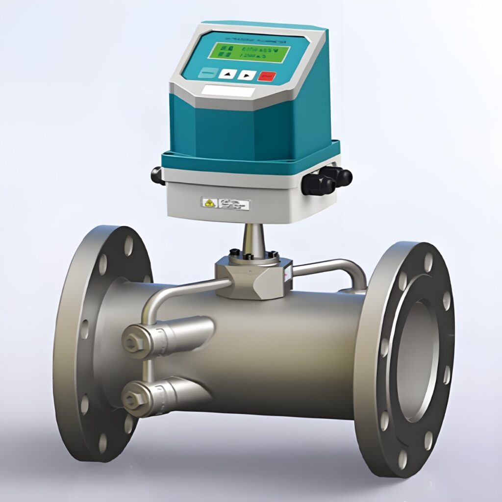
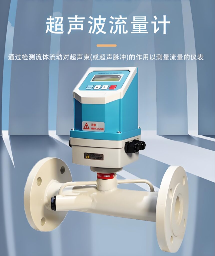
I. Site Selection: Laying the Foundation for Measurement
1. Straight Pipe Section Requirements
* Upstream straight pipe section ≥ 10 times the pipe diameter, downstream straight pipe section ≥ 5 times the pipe diameter, ensuring fluid stability (e.g., at least 1 meter upstream for DN100 pipes).
* Installation near bends, valves, pumps, or reducers is strictly prohibited, as these locations can cause flow turbulence and errors exceeding ±5%.
2. Environmental Selection
* Avoid interference sources: Keep away from high-electromagnetic-interference equipment such as frequency converters and welding machines (distance ≥ 2 meters) to avoid signal distortion.
* Avoid vibration: Choose an area with minimal vibration; install vibration damping pads if necessary.
* Temperature considerations: Ensure the ambient temperature is within the equipment’s operating range (typically -30℃ to +150℃).
3. Piping Conditions
* Material selection: Prioritize metal pipes with high acoustic impedance (carbon steel, stainless steel) to avoid thick-walled plastic pipes affecting the signal.
• Full Pipe Requirement: The pipe must always be filled with fluid. Partial filling or gas-liquid stratification will cause measurement failure.
• Vertical Pipe: If installation is necessary, ensure fluid flows from bottom to top to prevent air bubble accumulation.
II. Standard Installation: Ensuring Signal Quality
1. Pipe Surface Treatment
• Thorough Cleaning: Remove coatings and impurities with coarse sandpaper, then polish with fine sandpaper to below Ra 3.2μm (similar to a mirror finish).
• Key Note: Pipe surface roughness directly affects signal strength. Unpolished pipes may cause signal attenuation of 50% or more.
2. Installation Method Selection
* **V-Shaped Installation:** Suitable for pipes DN15-DN300mm. Two probes are symmetrically installed in a V-shape on the same side of the pipe. This is the standard installation method.
* **Z-Shaped Installation:** Suitable for pipes DN100mm and above, or pipes with severe scaling. Probes are installed on both sides of the pipe, resulting in minimal signal attenuation.
* **N-Shaped Installation:** Only suitable for small pipe diameters below DN50mm. Multiple sound wave reflections improve accuracy.
3. Coupling Agent Usage
* **Specialized Coupling Agent:** Silicone grease or a specialized coupling agent must be used. Ordinary grease or water cannot effectively transmit ultrasonic waves.
* **Application Technique:** Apply a uniform layer of approximately 7.5mm, eliminating all air bubbles. Otherwise, the signal strength may decrease by more than 30%.
* **Environmental Adaptation:** Use a high-temperature resistant coupling agent for high-temperature environments and a waterproof agent for humid environments. Regularly check for dryness.
III. Parameter Settings: Prerequisites for Measurement
1. Key Parameter Input
* **Pipe Parameters:** The pipe’s outer diameter and wall thickness must be accurately measured (using a thickness gauge). An error exceeding 1% will result in measurement errors. • Material Selection: Accurately select the pipe material (carbon steel, stainless steel, PVC, etc.), as different materials have significantly different sound velocities.
• Fluid Type: Differentiate between “clean water,” “sewage,” and “oil” modes, as these affect sound velocity calculations.
2. Installation Parameter Confirmation
• Sensor Spacing: Strictly follow the calculated values in the instruction manual during installation, ensuring errors are within acceptable limits.
* **Installation Angle:** The perpendicularity deviation between the sensor’s emitting surface and the pipe wall should be ≤ ±1°; otherwise, a measurement error of ±2% may occur.
* **Flow Direction:** Ensure the arrow on the meter body aligns with the water flow direction. Reversed installation will result in a negative measurement.
3. Temperature Compensation
* **Record Ambient Temperature:** The device will automatically correct for changes in sound velocity with temperature, but ensure the temperature sensor is functioning correctly.
* **Key Note:** A temperature deviation > 0.5℃ may increase the flow measurement error by 0.1-0.3%.
IV. Signal Adjustment: Verifying Installation Quality
1. Signal Strength Check
* **Ideal State:** Signal strength > 80%, signal quality (Q value) > 90, transmission time ratio within 100±3.
* **Troubleshooting:** If the signal strength < 60%, check the coupling agent, sensor position, or try the Z-method installation.
2. Signal Quality Optimization
* **Fine-tuning Technique:** Use the arrow keys to fine-tune the angle (±15°) until the signal quality display stabilizes in green.
• Common Issues:
o Large signal fluctuations: Usually caused by air bubbles in the fluid or insufficient straight pipe section; re-selection of the connection point is required.
o Complete signal loss: Check for empty pipe, insufficient coupling agent, or cable fault.
3. Zero Point Calibration
• Static Calibration: Zero point calibration is performed when the fluid in the pipeline is completely still to eliminate environmental interference.
• Small Signal Cutoff: Automatic cutoff is typically set when the flow rate is less than 5% of the full-capacity flow rate to prevent zero point drift.
V. Maintenance and Calibration: Ensuring Long-Term Stability
1. Routine Maintenance
• Coupling Agent Check: Check the condition of the coupling agent monthly. If cracks or bubbles appear, reapply.
• Clamp Loosening Check: Check the clamp tightness quarterly using a torque wrench (10-15 N·m).
• Environmental Monitoring: Record temperature and humidity changes at the installation point. Take protective measures if they exceed the specified range.
2. Calibration Cycle and Method
• Calibration Cycle: It is recommended to calibrate annually. Calibration should be performed immediately if the measured medium changes or after a major overhaul.
• Calibration Method:
o Static Calibration: Compare with a standard flow meter. The error should be ≤ ±1% (liquid) or ±2% (gas).
o Dynamic Calibration: Adjust host parameters under known flow rates to ensure signal strength ≥85%.
3. Common Problem Troubleshooting
• Signal Strength Drop: When signal strength drops by 50%, reapply coupling agent or check sensor location.
• Abnormal Data Fluctuations: Check fluid gas content, straight pipe length, or install a rectifier.
• Equipment Failure: First check ALC (signal strength) and AER diagnostic data, then troubleshoot power supply, cable issues, etc.
Special reminder: The accuracy of an ultrasonic flow meter depends 80% on the quality of installation, not the device itself. Proper operation can keep measurement errors within ±1%, while improper installation may cause errors exceeding 5%. For critical measurement points, it is recommended to use a portable ultrasonic flow meter for regular calibration to ensure data reliability.
Add me as a friend to learn more.





