

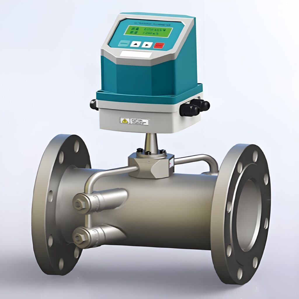
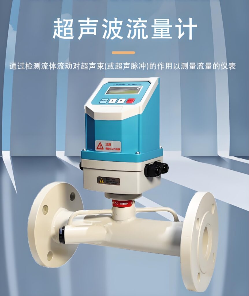
Setting the parameters of an ultrasonic flow meter is a crucial step in ensuring measurement accuracy. The core process includes equipment preparation, basic parameter input, installation parameter setting, signal debugging and calibration verification. Different types of flow meters (portable, fixed, insertion type) may have slight differences in specific operations, but the basic principles are the same.
I. Preparations Before Parameter Setting
1. Equipment Inspection and Environmental Confirmation
* Equipment Status Inspection: Confirm that the battery has sufficient power (>30%), the sensor connection is secure, and the coupling agent is applied evenly. Perform a benchmark test to ensure the “OK” green light remains constantly lit.
* Environmental Condition Confirmation:
* Temperature Range: -10℃~60℃ (Sensor operating temperature: -20℃~120℃)
* No strong electromagnetic interference (keep away from frequency converters, welding machines, etc.)
* No severe scaling on the pipe surface (error >2mm will affect accuracy)
2. Installation Location Selection
* Straight Pipe Section Requirements: Upstream straight pipe section ≥ 10 times the pipe diameter, downstream straight pipe section ≥ 5 times the pipe diameter. Avoid interference sources such as valves, pumps, and diameter reducers.
• Pipe Location Selection:
* Prioritize horizontal pipe sections or vertically upward flowing pipes.
* Avoid installation on vertical pipes with point outlets or free outlets.
* The pipe must be filled with fluid. II. Basic Parameter Setting Process 1. Pipe Parameter Setting
* Pipe Outer Diameter: Measure using calipers and input into window M11 (Menu+11).
* Pipe Wall Thickness: Measure at multiple points and take the average value, input into window M12 (Menu+12).
* Pipe Material Type: Select an option that matches the actual pipe material (e.g., carbon steel, stainless steel, PVC, etc.) and input into window M14 (Menu+14).
Lining Parameters: If there is an inner lining, enter the lining thickness and material in window M16 (Menu+16).
2. Fluid Parameter Settings
• Fluid Type: Select the option that matches the actual fluid (e.g., water, diesel, sewage, etc.), and enter it in window M20 (Menu+20).
• Fluid Characteristics:
o Clean Fluid: Select time-of-flight measurement
o Fluid Containing Particles/Bubbles: Select Doppler measurement
• Temperature Compensation: Record the ambient temperature; the device will automatically correct for changes in sound velocity.
3. Sensor Parameter Settings
• Sensor Type: Select the configured sensor type (e.g., bracket probe in the standard), and enter it in window M23 (Menu+23).
• Installation Methods:
* **V-method:** Suitable for pipe diameters of DN15-DN400mm. Two probes are symmetrically installed in a V-shape on the same side of the pipe.
* **Z-method:** Suitable for pipe diameters above DN100mm. Probes are installed on both sides of the pipe.
* **W-method:** Used for small-diameter pipes or low-turbidity liquids. Sound waves are reflected multiple times within the pipe.
* **Installation Distance:** Install the sensor according to the distance displayed in the M25 window. Typical positioning error should be <±10mm. III. Signal Debugging and Optimization 1. Signal Strength Debugging
* **Debugging Method:** Fine-tune the sensor angle (±15°) using the directional keys and observe the signal strength changes.
* **Ideal State:**
o Signal strength > 80% and signal quality display green
o Transmission time ratio within 100±3
o Q value (signal quality) > 75
· Common problem handling:
o Weak signal: Check if the coupling agent is sufficient and if the pipe surface is clean.
o Unstable signal: Avoid interference areas such as welds and valves. 2. Stable data acquisition
· Acquisition method: Keep the sensor still for 10 seconds, and record the data after the flow rate curve smooths out.
· Improve accuracy: Take the average of 3 consecutive measurements to reduce random errors.
· Special case handling:
o Gas content of medium > 3%: Enable the “Noise” function or use an insertion probe.
o Pipe ellipticity > 5%: Enable the “Circular Fitting” algorithm to improve accuracy. IV. Calibration and Verification 1. Zero point calibration
· Operation method: When the fluid in the pipe is still, perform a cut-off (eliminate zero point error) through the M22 menu.
· Importance: Ensure that the display is zero when there is no flow to avoid cumulative errors caused by zero point drift. 2. Instrument Coefficient Calibration
• Operation Method: Perform on-site calibration via the M26 menu, and calculate the actual flow rate/displayed flow rate ratio.
• Example: If the field test shows 90 L/m, but the panel displays 75 L/m, then the coefficient is 90/75 = 1.2. Set the coefficient to 1.25. 3. Verification Methods
• Standard Meter Comparison: Connect the standard flow meter and the flow meter being calibrated in series and compare the measurement results.
• Field Verification: Check the consistency between the cumulative flow and historical records, and observe the stability of the instantaneous flow. V. Special Setting Points for Different Types of Flow Meters 1. Portable Ultrasonic Flow Meter
• Quick Setting Tips:
o When the window displays M00-M09, press any number key x to directly enter the M0x window.
o Press the ENT key to directly enter the M90 window to check the signal quality.
• Mobile Measurement: Single measurement time ≤ 30 minutes (lithium battery protection). Avoid outdoor use during thunderstorms. 2. Fixed Ultrasonic Flow Meter
• Long-term stability settings:
o Set a low flow velocity cutoff value (usually 0.03 m/s) to avoid the accumulation of small flow errors.
o Configure data logging function and set a reasonable recording interval.
• Maintenance settings: Clean the sensor chip monthly (anhydrous ethanol + microfiber cloth).
3. Insertion Ultrasonic Flow Meter
• Special parameter settings:
o Set the insertion depth (usually 1/3 of the pipe diameter).
For high-viscosity fluids, the viscosity coefficient needs to be set.
* Installation Notes: Ensure the probe is in close contact with the inner wall of the pipe to avoid probe misalignment that could reduce signal strength. VI. Practical Tips and Troubleshooting 1. Parameter Setting Tips
* Quick Navigation: When the window displays M00-M09, press the . key to directly enter the M11 window.
* Parameter Saving: After setting, save in the M26 menu; otherwise, the parameters will reset after a power outage. 2. Common Problems and Solutions
* Problem: Low signal strength
* Solution: Re-grind the pipe surface, apply sufficient coupling agent, and check the sensor installation position.
* Problem: Large instantaneous flow fluctuations
* Solution: Adjust the probe position to improve signal strength, ensuring it meets the requirements for the first 10D and the last 5D.
* Problem: Inaccurate measurement values
* Solution: Check the accuracy of the pipe parameter input and confirm the appropriateness of the sensor installation method. 3. Maintenance Recommendations
* Daily Maintenance: Regularly clean the sensor surface, check the coupling agent condition, and avoid mechanical vibration/electromagnetic interference.
Calibration Cycle: Under normal operating conditions, calibration should be performed annually. Increased calibration frequency is required in harsh environments or critical applications.
Mastering the correct parameter setting methods is fundamental to ensuring the measurement accuracy of ultrasonic flow meters. First-time users are advised to follow the “Three Preparations – Five Steps – Three Pitfalls Avoidance” rule: prepare the environment, equipment, and parameters; complete the five measurement steps (positioning, debugging, data acquisition, calibration, and verification); and avoid the three common error sources: gas content in the medium, temperature fluctuations, and pipe deformation. With the introduction of AI algorithms, modern ultrasonic flow meters are developing towards “one-click intelligent calibration,” making future operation simpler and more efficient.
Add me as a friend to learn more.





