

The correct operation of temperature transmitter calibration specifications must follow the latest standard JJF 1183-2025. The core is to scientifically select calibration methods, reasonably arrange calibration points, and standardize the measurement process to ensure accurate and reliable measurement results.
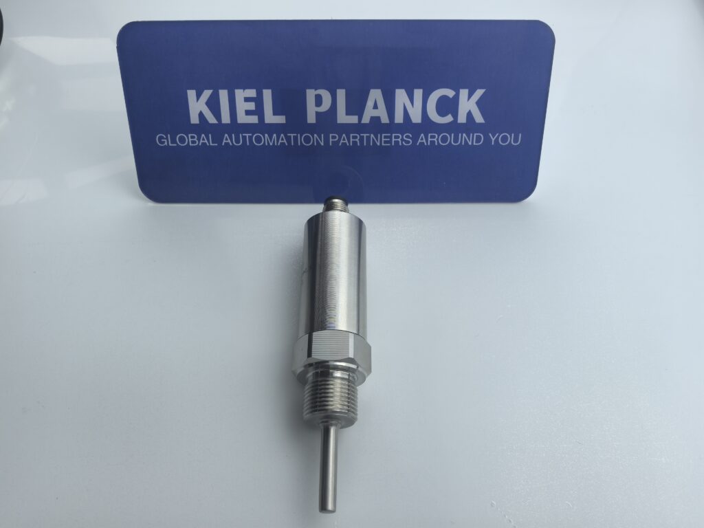
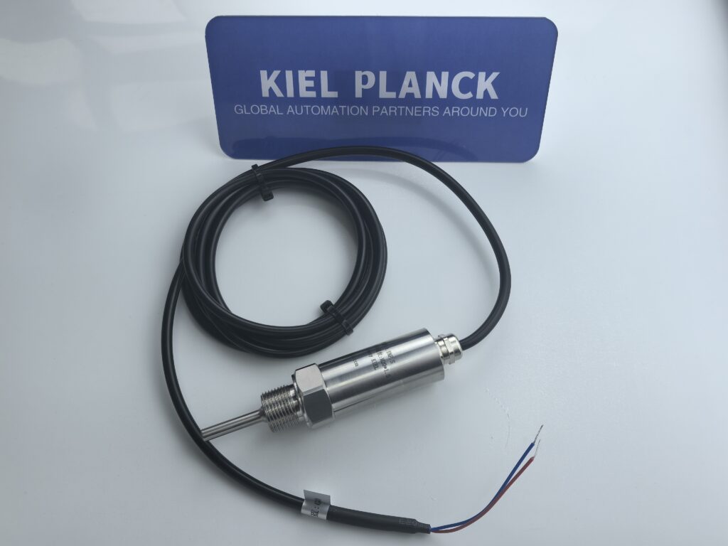
I. Preparations Before Calibration
1. Environmental Condition Confirmation
* Temperature Environment: The calibration environment temperature should be controlled within (20±5)℃ to avoid temperature fluctuations affecting measurement results.
* Humidity Requirements: Relative humidity should not exceed 85% to ensure equipment stability and measurement accuracy.
* Power Supply Preparation: Provide a stable 24V DC power supply. Voltage fluctuations should be controlled within ±1% to ensure normal transmitter operation.
2. Equipment and Tool Preparation
* Standard Temperature Source: Prepare a constant temperature bath or thermocouple calibration furnace to ensure temperature stability and uniformity.
* Measurement Standards: Prepare a standard resistance box, millivolt signal generator, standard ammeter, etc. The error of the standard should be less than 1/3-1/2 of the error of the instrument being calibrated.
* Connecting Wires: Select dedicated connecting wires that meet the requirements. When using a three-wire connection, minimize the difference in resistance between the wires.
* Preheating Equipment: Ensure the transmitter is preheated for at least 5 minutes before calibration to allow the circuit to reach a stable state.
3. Transmitter Status Check
* • Visual Inspection: Confirm the transmitter is clean and tidy, with all parts intact and the nameplate and markings complete and clear.
• Internal Inspection: Inspect the circuit board, terminals, and internal wiring to ensure there is no looseness, corrosion, or damage.
• Sealing Check: Confirm the transmitter has good sealing performance to prevent external interference from affecting the measurement results.
II. Calibration Method Selection and Operation Procedures
1. Calibration Method Selection
* **Calibration with Sensor:** Insert the transmitter’s sensing element into a standard temperature source. Suitable for applications requiring high accuracy or where sensor performance is questionable.
* **Calibration without Sensor:** Disconnect the transmitter’s sensing element and use a standard resistance source and process testing equipment. Suitable for routine maintenance and applications with lower accuracy requirements.
2. Calibration Operation Procedures
1. Equipment Connection:
* **Calibration with Sensor:** Insert the transmitter sensor into the temperature source, close to a standard thermometer.
* **Calibration without Sensor:** Connect the transmitter’s input terminal to a standard resistance box or millivolt signal generator.
* Connect the output terminal to a standard ammeter or voltmeter, ensuring a secure connection.
2. Pre-Calibration Adjustment:
* With the sensor disconnected, adjust the lower and upper limits of the output by changing the input signal.
* Ensure the output value matches the theoretical lower and upper limits, guaranteeing accurate range measurement.
3. Calibration Point Measurement:
* Starting from the lower limit, steadily increase the input signal (upward stroke) and measure each calibration point sequentially.
• After the temperature inside the temperature source has stabilized sufficiently (generally at least 30 minutes), proceed with the measurement.
• Then, reverse the direction, decreasing the input signal from the upper limit (downward stroke) and measure each calibration point sequentially.
4. Data Recording:
* Record the standard input value and transmitter output value at each calibration point.
* Take alternating readings of the standard thermometer reading and the transmitter output to reduce systematic errors.
III. Calibration Point Selection and Measurement Techniques
1. Calibration Point Selection Principles
* Quantity Requirement: At least 5 points, including upper and lower limits, to ensure coverage of the entire range.
* Distribution: Calibration points should be evenly distributed across the temperature range, especially around 50% of the range.
* Typical Point Selection: For a 0-100℃ range, 0℃, 25℃, 50℃, 75℃, and 100℃ can be selected as calibration points.
2. Measurement Techniques
* Temperature Stability Judgment: Using a standard thermometer, a temperature change ≤0.03℃ within 10 minutes is considered stable.
* Multi-point Measurement: Perform at least 3 measurements at each calibration point and take the average value to reduce random errors.
* Forward and Reverse Strokes: Both upward and downward stroke measurements must be performed to evaluate the transmitter’s hysteresis error.
* Cold junction compensation: When calibrating a thermocouple transmitter, the input signal value should be reduced by the millivolt value corresponding to the thermocouple’s graduation number at room temperature.
IV. Data Processing and Result Evaluation
1. Error Calculation
• Basic error formula: Δ = [(I_measured – I_actual)/I] × 100% or Δ = [(V_measured – V_actual)/V] × 100%
o I_measured/V_measured: Measured output value of the temperature transmitter
o I_actual/V_actual: Theoretical output value at the calibration point
o I/V: Difference between the upper and lower limits of the temperature transmitter output
2. Data Processing Principles
• Decimal Point Retention: In measurement results and error calculations, the number of decimal places retained should be limited to 1/10 to 1/20 of the transmitter’s permissible error due to rounding error.
• Uncertainty Assessment: Measurement uncertainty assessment should be performed. The uncertainty should be less than 1/33 of the permissible error value. Result Evaluation
• Accuracy Class Judgment: Compare the calculated error with the transmitter’s nominal accuracy class (e.g., 0.5, 1.0).
• Acceptance Criteria: The error should not exceed the error specified by the transmitter’s RTD itself.
• Calibration Conclusion: Issue a calibration certificate, indicating the calibration results, uncertainty, and recalibration time interval.
V. Common Problems and Solutions
1. Common Problems During Calibration
• Unstable Temperature: Large temperature fluctuations within the temperature source lead to inaccurate measurement results.
• Wiring Errors: Reversed or loosely connected compensation wires affect signal transmission.
• Insufficient Cold Junction Compensation: Failure to properly consider cold junction temperature leads to measurement errors in the thermocouple transmitter.
• Sensor Failure: Open circuit, short circuit, or intermittent open/short circuit in the sensor can affect measurement results.
2. Troubleshooting
• Unstable Temperature: Extend the preheating time to ensure the temperature source is stable for at least 30 minutes before measurement.
• Wiring Incorrectness: Check the wiring diagram to ensure the compensating wires match the thermocouple type and are securely connected.
Cold Junction Compensation: Use a high-precision temperature sensor to measure the cold junction temperature, avoiding errors caused by using ordinary thermometers.
· Sensor Failure: Check the sensor status, replace the damaged sensor, and then perform calibration.
VI. Calibration Cycle and Maintenance Recommendations
1. Calibration Cycle Determination
· Routine Equipment: It is recommended to calibrate every 12 months to ensure measurement accuracy.
· Critical Equipment: For critical temperature measurement points in safe production processes, it is recommended to calibrate every 6 months.
· Special Environments: For transmitters used in high-temperature, high-humidity, or corrosive environments, the calibration cycle should be appropriately shortened.
2. Maintenance Recommendations
· Regular Inspection: Check the transmitter’s appearance, wiring, and display status monthly.
· Cleaning and Maintenance: Keep the transmitter clean to avoid dust and oil affecting measurement performance.
· Environmental Control: Ensure the transmitter operates in an environment of -25℃ to +70℃ to avoid the effects of extreme temperatures.
· Probe Depth: The probe insertion depth should be 1/2 to 2/3 of the media pipeline diameter to ensure measurement accuracy.
3. Special Precautions
· Safety Requirements: When used in intrinsically safe explosion-proof systems, a matching isolation safety barrier must be used.
· Disassembly Principles: Disassembly of the transmitter while the power is on is generally prohibited. Replacement or disassembly must be performed with the power off.
· Insulation Testing: Periodically test the output terminal resistance to the housing to >10MΩ, and the insulation resistance of the measurement circuit to ground to >20MΩ.
Following the above procedures ensures the accuracy and reliability of temperature transmitter calibration results, providing reliable temperature measurement assurance for industrial production processes. For applications requiring high precision, it is recommended to use a calibration method with a sensor and perform the calibration in a laboratory environment to obtain the best results.
Add me as a friend to learn more.





