

Temperature transmitters are instruments that convert temperature variables into standardized output signals that can be transmitted. They are mainly used for the measurement and control of temperature parameters in industrial processes. They achieve the conversion of temperature into electrical signals through sensors such as thermocouples or resistance temperature detectors (RTDs), and are widely used in industries such as petrochemicals, power, and metallurgy.

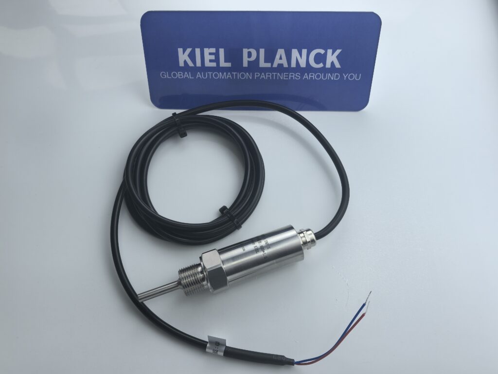
I. Definition of Temperature Transmitter
A temperature transmitter is an instrument that converts temperature variables into a standardized, transmittable output signal. Its core function is to convert physical temperature signals into standard electrical signals that are easy to transmit and process over long distances, such as 4-20mA current signals, 0-5V/0-10V voltage signals, or RS485 digital signals.
From a technical perspective, a temperature transmitter typically consists of two parts:
* **Sensor Section:** Primarily uses thermocouples or resistance temperature detectors (RTDs) as the temperature sensing element.
* **Signal Conversion Section:** Includes a measurement unit, signal processing and conversion unit, responsible for converting the sensor signal into a standard output signal.
II. Working Principle of a Temperature Transmitter
1. Basic Workflow
The working principle of a temperature transmitter can be summarized in the following steps:
* **Temperature Detection:** Thermocouples or RTDs convert temperature changes into electrical signals (thermoelectric potential or resistance changes).
* **Signal Processing:** Signals are processed through circuits such as voltage regulation filtering, operational amplification, and nonlinear correction.
* **Signal Conversion:** Signals are converted into a standard output signal through V/I conversion, constant current, and reverse protection circuits.
2. Core Technology: Thermocouple Transmitter
• Amplify the thermoelectric potential generated by the thermocouple after cold junction compensation.
• Eliminate nonlinear errors in the relationship between thermoelectric potential and temperature through a linearization circuit.
• Convert to a 4-20mA current output signal for the RTD transmitter.
• Convert the resistance change of the RTD into a voltage signal.
• Eliminate lead resistance errors using a three-wire or four-wire system.
• Convert the resistance-temperature relationship to a linear output through nonlinear correction.
3. Key Technical Features
• Cold junction compensation: Thermocouple transmitters must undergo cold junction temperature compensation because thermocouples measure the temperature difference between two points, not the temperature itself.
• Nonlinear correction: The resistance-temperature relationship of an RTD is nonlinear. The transmitter’s internal circuitry performs linearization processing to make the output signal linearly related to temperature.
• Isolation technology: Electromagnetic isolation between input, output, and power supply improves anti-interference capability and system stability.
III. Main Types of Temperature Transmitters
1. Classification by Temperature Sensing Element
• Thermocouple transmitters: Suitable for high-temperature measurements (-200℃~1800℃), such as K, E, and B type thermocouples.
• Resistance temperature detector (RTD) transmitters: Suitable for medium- and low-temperature measurements (-200℃~850℃), such as PT100, PT1000, Cu50, and Cu100.
2. Classification by power supply wiring method
Two-wire system: Most commonly used, power and signal share a single wire, long transmission distance, low installation cost.
• Three-wire/Four-wire system: Used for high-precision measurement, eliminating the influence of lead resistance.
3. Classification by Function and Intelligence Level
• Standard type: Basic signal conversion function
• Digital display type: With LCD or LED display, can display temperature values on-site.
• Intelligent type: Supports communication protocols such as HART and Modbus, can be remotely configured, calibrated, and monitored.
IV. Applications of Temperature Transmitters
1. Main Application Areas
• Petrochemical industry: Monitoring the temperature of reactors, storage tanks, and pipelines to ensure safe production.
• Power industry: Monitoring the temperature of generators, transformers, and other equipment to prevent overheating faults.
• Metallurgical industry: Controlling the temperature of high-temperature equipment such as steelmaking furnaces and rolling mills.
• Food and pharmaceutical industry: Precisely controlling the temperature of equipment such as sterilizers, cold storage, and fermentation tanks.
• HVAC: Achieving automatic adjustment and control of indoor temperature.
2. Application Advantages
• Long-distance transmission: 4-20mA signals are suitable for long-distance transmission and have strong anti-interference capabilities.
Cost-saving: Two-wire design eliminates the need for dedicated compensating wires, reducing installation costs.
Improved accuracy: Built-in cold junction compensation and nonlinear correction functions improve measurement accuracy.
Easy integration: Standardized output signals facilitate integration with control systems such as DCS/PLC.
3. Typical Application Scenarios
• Industrial Process Control: e.g., PID closed-loop temperature control for reactors
• Energy Management: Boiler piping temperature monitoring to optimize energy efficiency
• Environmental Testing: Support for extreme environmental temperatures in high and low temperature chambers
• GMP Workshops: Remote calibration and data traceability in the food and pharmaceutical industries
V. Development Trends of Temperature Transmitters
1. Intelligentization
• Supports communication protocols such as HART, Modbus, and Profibus for device networking
• Built-in self-diagnostic function, automatically switching to safe output
• Remote parameter control via handheld devices or PCs, simplifying on-site debugging
2. High Precision and High Reliability
• Measurement accuracy is continuously improving, reaching ±0.1℃ or even higher
• Use of high-quality materials (e.g., 316L stainless steel) to improve corrosion resistance
• Improved encapsulation processes (e.g., epoxy resin casting) enhance environmental adaptability
3. Multifunctional Integration
• Integration of multiple functions such as temperature measurement, display, alarm, and communication
• Supports multiple sensor inputs (thermocouples, RTDs, thermistors, etc.)
· Offers multiple output options (4-20mA, 0-5V, RS485, etc.)
4. Miniaturization and Modularization
• Continuously shrinking size (e.g., 95×37×32mm)
• Modular design facilitates installation and maintenance
• Widespread adoption of standard DIN 35mm mounting methods
Temperature transmitters, as key equipment in industrial automation, are constantly evolving with the development of technologies such as the Internet of Things and big data. In the future, they will become more intelligent and integrated, providing reliable temperature measurement and control solutions for industrial processes.
Add me as a friend to learn more.





