

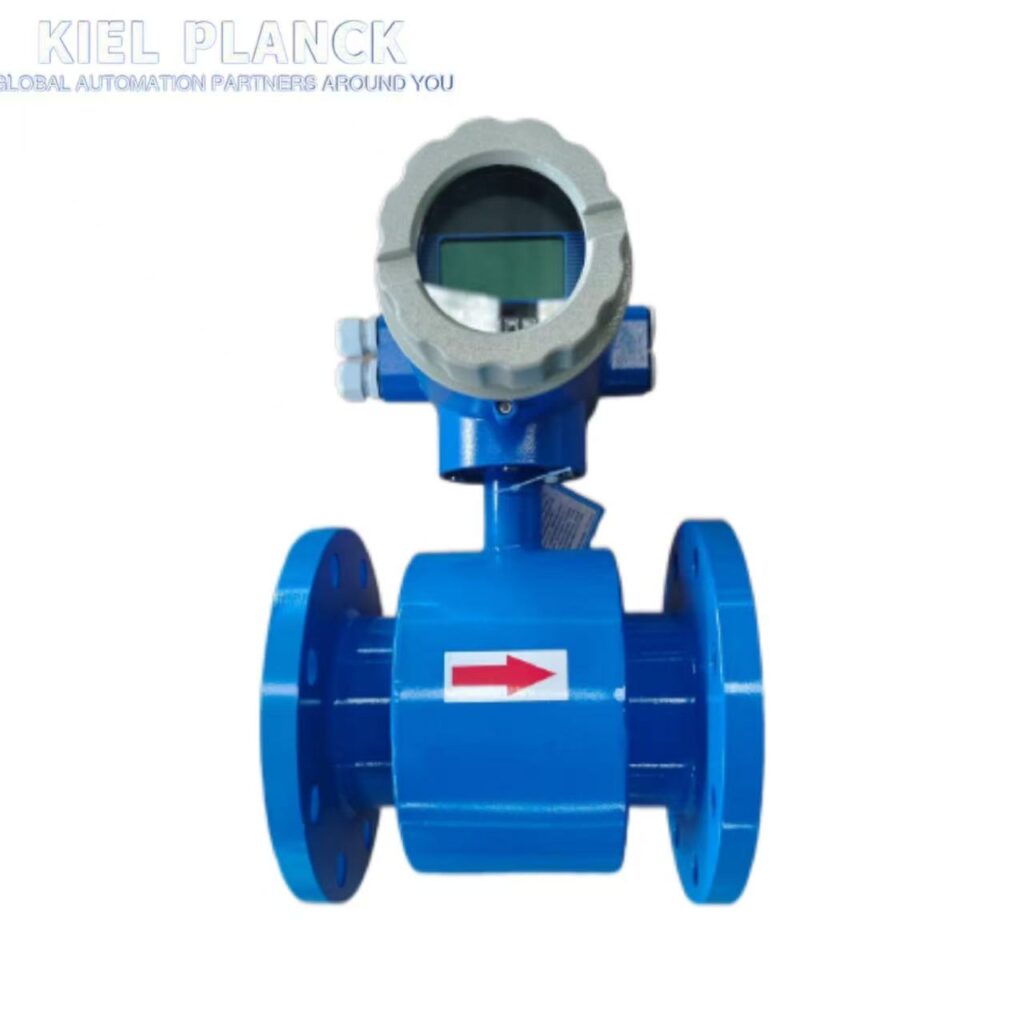
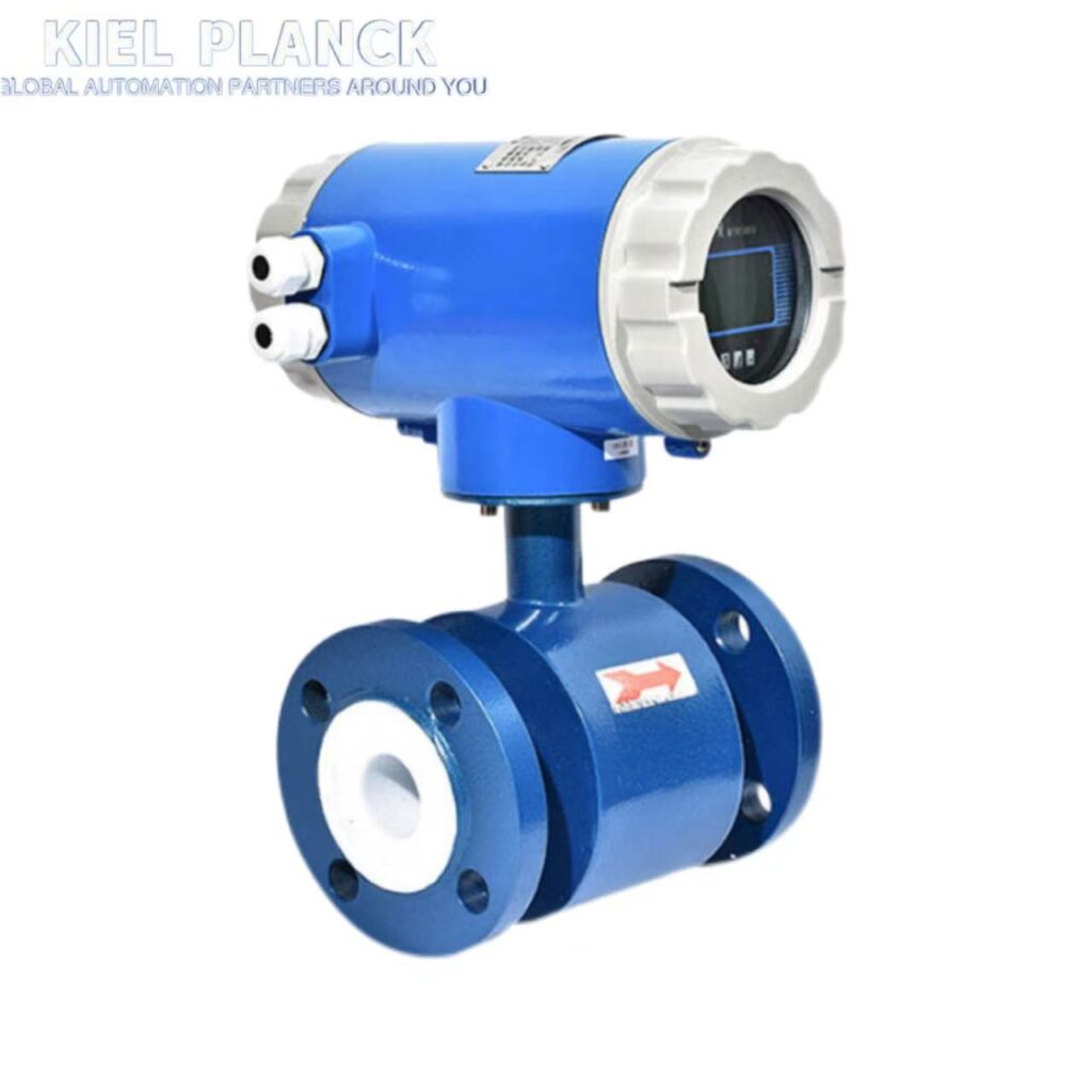
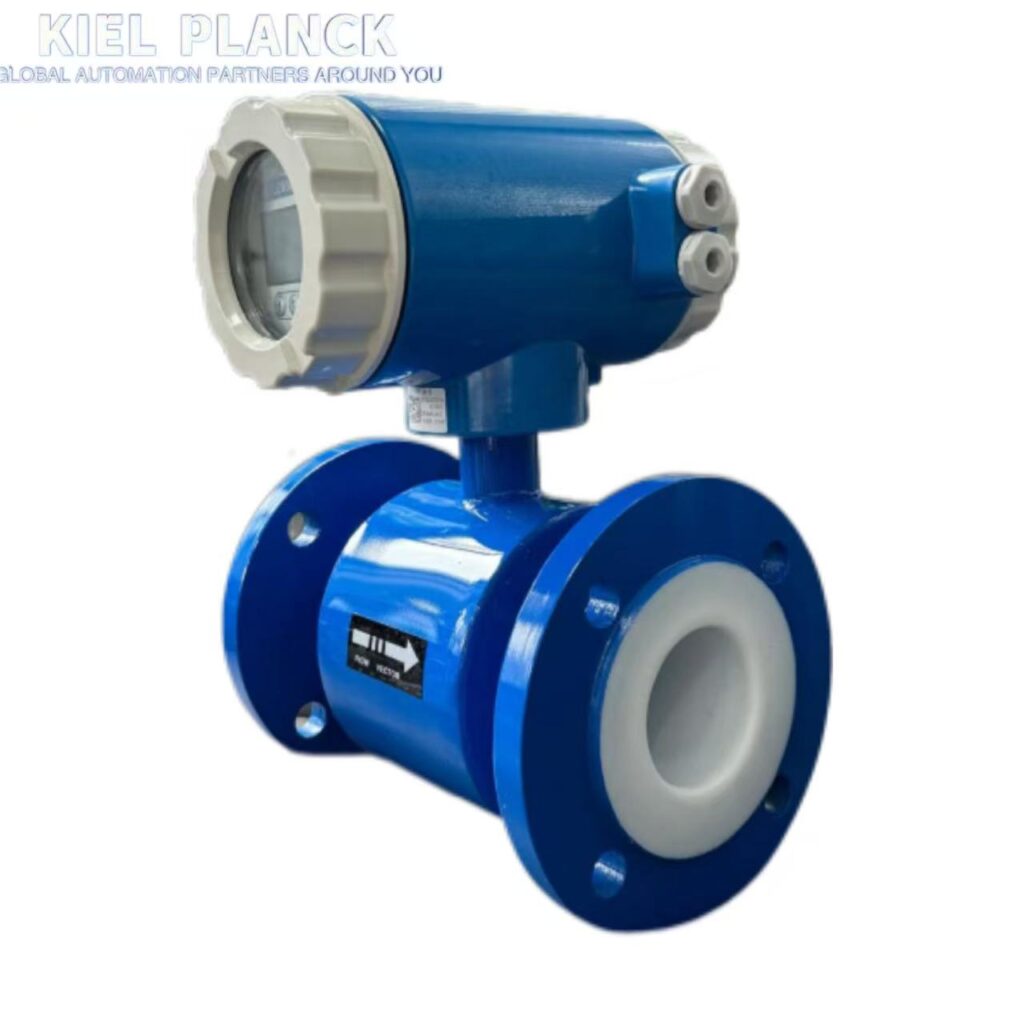
The design of electromagnetic flowmeters needs to comprehensively consider measurement accuracy, environmental adaptability, and long-term stability. By optimizing electrode structure, signal processing algorithms, and material selection, common problems such as medium fluctuations, electromagnetic interference, and the influence of deposited layers can be effectively solved, ensuring reliable measurement in complex industrial scenarios.
I. Core Design Considerations
1. Electrode and Sensor Design
Electrode Material Selection: Corrosion-resistant materials are selected based on the characteristics of the medium, such as Hastelloy C (resistant to oxidizing acids), tantalum (resistant to hydrochloric acid and chlorides), and titanium (resistant to seawater and chlor-alkali). In environments with conductivity fluctuations of ±50%, the multi-engine adaptive algorithm can control the measurement error within 0.5%.
Electrode Structure Optimization: Asymmetric design is adopted to reduce the impact on fluid flow. Micro-machining technology improves processing accuracy and reduces electrode corrosion and wear.
Electrode Position: The installation position should preferably be perpendicular to the pipeline to prevent sediment accumulation from affecting measurement accuracy. It should be flush with the lining to avoid obstructing fluid flow.
2. Magnetic Field System Design
Magnetic Field Strength Optimization: An appropriate magnetic field strength is selected based on the fluid conductivity and flow velocity to ensure a stable induced electromotive force signal.
Alternating Magnetic Field Application: Modern electromagnetic flowmeters generally use alternating magnetic fields instead of direct current magnetic fields to avoid measurement errors caused by electrolyte liquid polarization.
Excitation coil design: It is wound with high-quality copper core enameled wire with a resistance greater than 200MΩ to ensure good insulation performance.
3. Signal Processing System
High-Precision AD Conversion: Utilizes the ADS1115 high-precision AD conversion chip, paired with an LM324 operational amplifier, to amplify the induced electromotive force by 1000 times, and then filter out power frequency interference.
Digital Signal Processing: Employs a Kalman filter algorithm to eliminate signal fluctuations caused by electromagnetic interference in industrial environments, tracking flow changes more quickly than the moving average algorithm.
Multi-Parameter Fusion Compensation: Integrates an intelligent compensation mechanism for 12 influencing factors, including temperature, pressure, and conductivity, improving measurement accuracy.
4. Structure and Material Selection
Measuring Conduit Material: Employs non-magnetic, low-conductivity, and low-thermal-conductivity materials, such as non-magnetic stainless steel, fiberglass, high-strength plastics, and aluminum.
Liner Material Selection:
Measuring Conduit Material: Employs non-magnetic, low-conductivity, and low-thermal-conductivity materials, such as non-magnetic stainless steel, fiberglass, high-strength plastics, and aluminum.
Lining Material Selection:
PTFE/PFA: Resistant to highly corrosive media (such as hydrofluoric acid), temperature range -10℃~+160℃
F46: Suitable for high-temperature corrosive liquids
Abrasion-resistant rubber: Suitable for measuring slurries, cement slurries, etc., containing solid particles
Protection Rating: Sensor protection rating reaches IP68, converter protection rating is not less than IP65, adaptable to harsh environments.
II. Key Issues and Solutions
1. Dielectric Conductivity Fluctuation Issue
Multi-engine Adaptive Algorithm: Real-time monitoring of dielectric conductivity changes, automatic switching of computational models. Measured data shows that within a conductivity fluctuation range of ±50%, measurement errors can be controlled within 0.5%.
Electrode Material Optimization: Selecting appropriate electrode materials for different conductivity ranges. For example, standard electrodes can be used for media with conductivity ≥5μS/cm, while low-conductivity media require special design.
Flow Rate Adjustment: When measuring low-conductivity liquids close to the threshold, selecting the lowest possible flow rate (less than 0.5~1m/s) avoids increased flow noise leading to output fluctuations.
2. Electromagnetic Interference Issue
Real-time Algorithm Synchronization Mechanism: Employing a dual-core processor architecture ensures that the time difference between signal acquisition and processing is less than 1ms, improving system stability in environments with strong electromagnetic interference.
Shielding Design: Signal lines use shielded cables, spaced at least 15cm apart from power lines, and run separately within metal conduits.
Grounding specifications: The flowmeter’s casing, shielding wire, and measuring conduit must all have separate grounding points. They must not be connected to the motor or the upper and lower pipes. The grounding resistance should be <10Ω.
3. Deposits and Scaling Issues
Intelligent Compliance Verification System: Built-in 28 verification standards monitor the compliance of measurement data in real time, automatically identifying the impact of deposits on the inner wall and eliminating them through algorithmic compensation.
Flow Rate Optimization: For fluids with substances prone to adhesion, deposition, and scaling, a flow rate of at least 2 m/s is selected, and increased to 3-4 m/s or higher, providing self-cleaning and preventing adhesion and deposition.
Electrode Design: Utilizing a scraper-type electrode structure or electrodes made of special materials reduces the impact of deposits on measurement accuracy.
4. Installation and Environmental Adaptability
Installation Position Optimization: Vertical installation is preferred, and the measured fluid must flow from bottom to top; for horizontal installation, ensure both electrodes are on the same horizontal plane and that the measuring conduit is always filled with liquid.
Straight Pipe Section Requirements: A straight pipe section of approximately 10 times the pipe diameter must be present before the electromagnetic flowmeter to eliminate the influence of various local resistances on the symmetry of the streamline distribution.
Environmental adaptability design: The sensor is characterized by minimal impact from ambient temperature, with the effect of ambient temperature changes being <±0.1%/10°C, ensuring measurement accuracy in areas with large temperature differences.
5. Low Power Consumption and Intelligent Design
Low Power Circuitry: Optimized circuit design reduces circuit losses; low-power components are used to extend equipment lifespan.
Wireless Transmission Technology: Utilizes low-power wireless communication modules (such as Bluetooth and ZigBee) for remote monitoring and data acquisition, reducing cable costs and installation complexity.
Self-Diagnostic Functions: Built-in functions include empty pipe detection, flow alarm, and small signal cutoff to promptly detect and handle abnormal situations.
III. Typical Application Scenarios
1. Chemical Industry Applications
Corrosion-Resistant Design: Employs PTFE lining and Hastelloy electrodes, resistant to corrosive media such as strong acids, strong alkalis, and high salts.
Explosion-Proof Certification: Equipped with Ex d IIC T6 or Ex ia IIC T4 explosion-proof certification to ensure safe operation in explosive environments.
Compact Design: Suitable for confined spaces, such as plug-in or clamp-on installations, adaptable to complex piping layouts.
2. Water Treatment Industry Applications
**Unobstructed Flow Design:** The measuring tube contains no components that impede fluid flow, resulting in zero pressure loss, making it suitable for high-velocity water treatment systems.
**High-Precision Measurement:** Accuracy typically reaches ±0.5% to ±1%, meeting the water treatment industry’s requirements for precise flow control.
**Strong Corrosion Resistance:** The sensor is made of corrosion-resistant materials, enabling long-term stable operation in harsh environments.
3. Steel Industry Applications
High Temperature Adaptability: The sensor can withstand a temperature range of -25℃ to +180℃, suitable for the high-temperature environment of the steel industry.
Wear-Resistant Design: Utilizing wear-resistant linings and electrodes, it is suitable for measuring cooling water and slurry containing solid particles.
Strong Anti-Interference Capability: Employing a special shielding and grounding design to address the strong electromagnetic interference environment of the steel industry.
IV. Design Verification and Quality Assurance
Strict Factory Testing: Establishing standard devices for DN3-DN2200 mass flow rate and DN15-DN300 sonic nozzle gas flow rate to ensure that every electromagnetic flowmeter leaving the factory meets high-standard quality requirements.
On-Site Calibration and Verification: It is recommended to calibrate annually for ordinary media and every 3-6 months for corrosive media to ensure long-term measurement accuracy.
Full Lifecycle Management: Providing full lifecycle services from pre-sales technical consultation and on-site condition assessment to after-sales maintenance to ensure long-term stable operation of the equipment.
The design of electromagnetic flowmeters requires comprehensive consideration of media characteristics, environmental conditions, and measurement requirements. High-precision and high-reliability flow measurement can only be achieved in complex industrial environments through the synergistic effect of material selection, structural optimization, and intelligent algorithms. For special operating conditions, it is recommended to collaborate with specialized manufacturers for customized designs to meet specific application needs.
If you want to know more, please contact me.





