

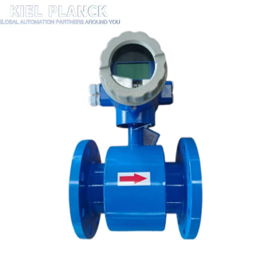
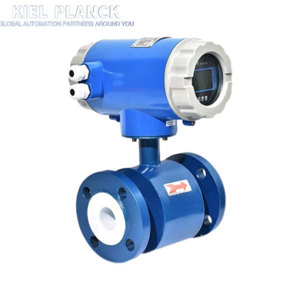
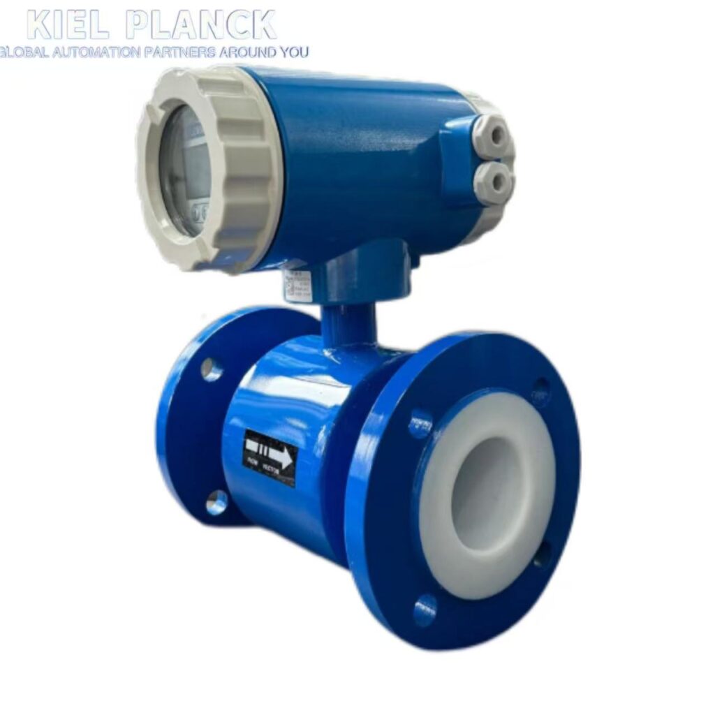
Modifying the range and coefficient of an electromagnetic flowmeter is a crucial operation to ensure measurement accuracy. It must be done through professional parameter settings. It is not recommended that non-professionals adjust it arbitrarily, otherwise it may lead to serious measurement inaccuracies.
I. Range Adjustment Method
1. Basic Concepts
The range refers to the measurable range Qmin to Qmax of the flow meter.
A reasonable range should cover 20% to 80% of the actual flow rate, avoiding prolonged operation at the lower limit (<10%) or beyond the range.
2. Range Adjustment Steps
Enter the settings menu: Enter the password (usually “0000” or “181818”) as per the equipment manual to activate parameter settings.
Locate the range parameters:
Find the “range” or “range setting” option.
Some models require selecting “quickSETUP” → “AnalogOUTPUTS” first.
Modify the range value:
Enter the new Qmin and Qmax (e.g., 0–300 m³/h).
Ensure it matches the actual flow rate on site.
Save settings:
Press the “OK” button to save the new range.
Some models require selecting “yes” and confirming again.
3. Measurement Range Adjustment Techniques
Expanding the Measurement Range: Try increasing the K-coefficient or replacing the sensor with a larger diameter (e.g., DN50 → DN65).
Reducing the Measurement Range: Decrease the K-coefficient or select a smaller diameter sensor.
Over-range Handling: If the flow rate exceeds the design range, prioritize process adjustments or replacing the sensor with one of suitable range.
II. Coefficient Modification Method
1. K-Coefficient Principle
The K-coefficient is the core parameter of the flow meter, with the following relationship: Q = K × f (Q is the flow rate, f is the frequency signal)
It has been calibrated at the factory using actual flow, but adjustments are needed due to changes in the characteristics of the medium in the field.
2. Coefficient Modification Calculation Formula
When the actual expected flow rate is Q2, the current instantaneous flow rate is Q1, and the original K-coefficient is K1:
K2 = (Q2 / Q1) × K1
Example: Currently displayed Q1=54.28, K1=1.5372, actual flow rate Q2=60.33
Then: K2 = (60.33/54.28) × 1.5372 = 1.7085
Enter the K2 value into the meter to replace the original K1.
3. Steps to Modify the K Coefficient
Enter Parameter Settings: Enter the password to access the menu system.
Locate the K coefficient option: Usually under the “Instantaneous Flow Parameter” or “Instrument Coefficient” menu.
Enter the New K Value: Enter the new coefficient based on the calculation results.
Save and Verify: After saving, zero-point calibration and full-scale verification are required.
III. Key Precautions
1. Preparation Before Adjustment
Record original parameters: to avoid irreversible errors.
Confirm medium characteristics: conductivity, viscosity, temperature, etc., affect adjustment results.
Check installation conditions: ensure the straight pipe section meets requirements (5D before, 3D after).
2. Verification After Adjustment
Zero-point calibration: close the valve and perform empty pipe calibration with no flow.
Full-stroke verification: use a standard gauge or known flow rate for comparative testing.
Dynamic testing: observe whether the response is stable under different flow rates.
3. Professional Advice
Regular Calibration: For ordinary media, once a year; for corrosive media, once every 3-6 months.
Professional Operation: Adjustments by non-professionals may increase errors. It is recommended to contact the manufacturer’s technical staff.
Range Redundancy: Reserve 20% range redundancy when selecting a model to avoid frequent adjustments.
IV. Common Problem Handling
Large Fluctuations After Adjustment: Check grounding reliability and increase damping time (2-10 seconds).
No Signal Output: Confirm medium conductivity > 5μS/cm; check for electrode short circuits.
Zero Drift: Re-zero the device using an empty pipe; check for sensor tilt.
Important Reminder: Electromagnetic flowmeter adjustment involves multiple parameters. It is not recommended to solve all problems by adjusting only a single parameter. If a significant range adjustment is required (e.g., increasing by more than 10 times), consider replacing the sensor rather than just modifying parameters; otherwise, the measurement error at low flow rates will increase significantly. For professional guidance, it is recommended to contact the flowmeter manufacturer’s technical support.
If you want to know more, please contact me.





