

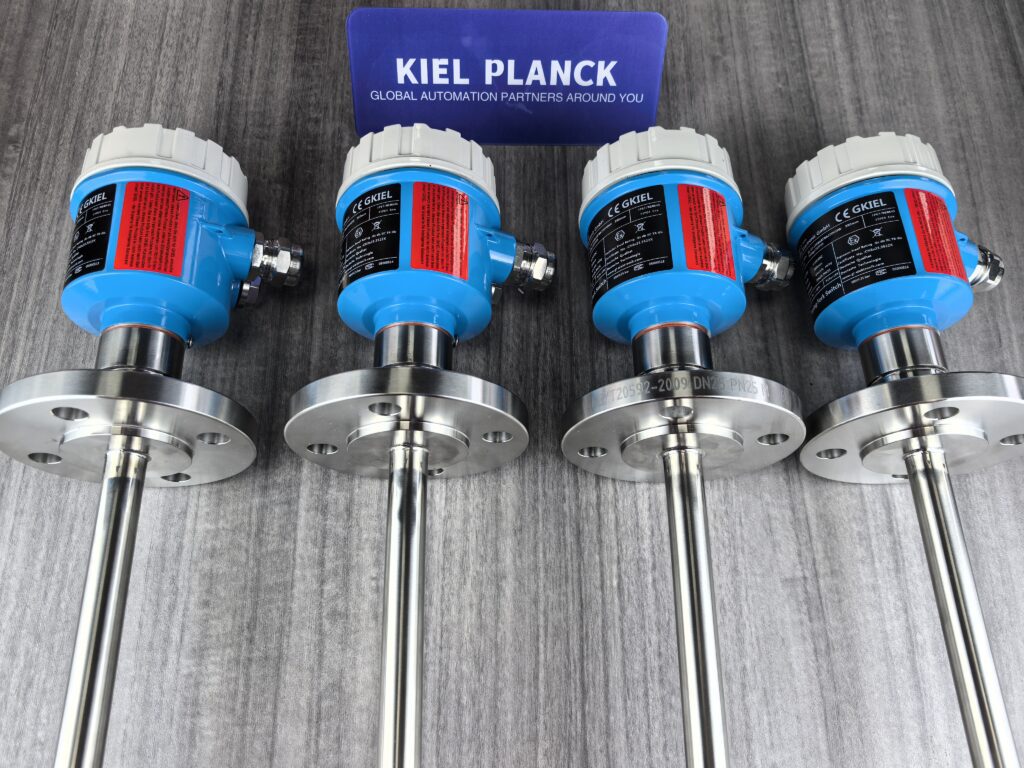
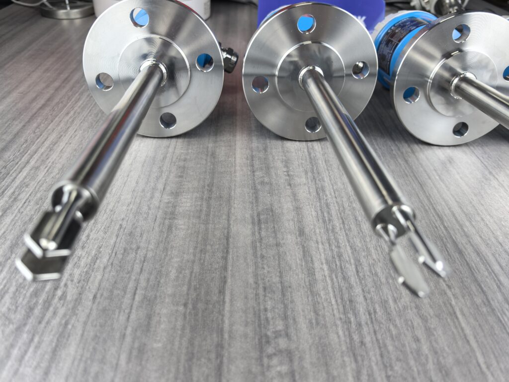
Tuning fork densitometers accurately determine liquid density by measuring changes in vibration frequency. The core principle is that liquid density is inversely proportional to the vibration frequency of the tuning fork; that is, the higher the density, the lower the vibration frequency, and vice versa.
I. Basic Physical Principles
1. Vibration Characteristics Fundamentals
A tuning fork vibrates continuously at its natural frequency under the drive of a piezoelectric crystal.
When the tuning fork is immersed in a liquid, the liquid density affects the effective mass of the vibrating system, causing a change in the resonant frequency.
Physical Relationship: The vibration frequency f is inversely proportional to the effective mass m of the system (f ∝ 1/√m)
Density Influence: The higher the liquid density, the greater the mass attached to the tuning fork, and the lower the vibration frequency.
2. Mathematical Model
There is a strict mathematical relationship between the medium density and the vibration frequency: ρ = K₀ + K₁T + K₂T²
ρ: Density of the measured medium
T: Natural frequency of the tuning fork
T²: Frequency of the measured medium flowing through the fork
K₀, K₁, K₂: Instrument constants (calibrated at the factory using a standard medium)
3. Typical Frequency Reference Values
Air: Vibration frequency approximately 1000 Hz
Oil: Vibration frequency approximately 700 Hz
Water: Vibration frequency approximately 600 Hz Hz By comparing the actual measured frequency with these reference values, the liquid density can be accurately calculated.
II. Instrument Structure and Workflow
1. Core Components
Tuning fork probe: Made of 316L stainless steel or Hastelloy, directly contacts the measured medium.
Piezoelectric crystals: One drives vibration, the other detects frequency changes.
Transmitter/Electronic Unit: Contains a microprocessor for signal processing, calculation, and diagnostics.
Temperature sensor: Typically PT100, used for automatic temperature compensation.
2. Workflow
Excitation Stage: The electronic unit stabilizes the tuning fork at its natural resonant frequency through phase shifting and amplification circuits.
Measurement Stage: As the liquid flows through the tuning fork, density changes cause a change in the resonant frequency.
Signal Processing: The transmitter detects the frequency change and calculates the density value using a preset mathematical model.
Temperature Compensation: A built-in temperature sensor eliminates the influence of temperature fluctuations on the measurement results.
Output Results: Density values are output via a 4-20mA signal, RS485, or digital display.
III. Technical Features
1. High-Precision Measurement
Measurement Accuracy: Up to ±0.001 g/cm³ (±1 kg/m³)
Repeatability: Up to ±0.0002 g/cm³ (±0.2 g/cm³) (kg/m³) Resolution: Up to 0.0001 g/cm³, capable of detecting minute density changes.
2. Wide Applicability
Measurement Range: 0.5–2.5 g/cm³ (500–2500 kg/m³)
Viscosity Compatibility: Meets fluids with viscosities up to 20000 cP
Temperature Range: -50℃ to +200℃, meeting extreme operating conditions
Media Type: Meets mixed media containing solid particles or bubbles
3. Practical Advantages
No moving parts: Robust structure, not prone to clogging, low maintenance
Fast response: Real-time online monitoring, no manual sampling required
Easy installation: Can be directly installed on pipelines or storage tanks, with both T-type side-opening insertion and retractable installation methods available
Multi-functional output: Can simultaneously calculate parameters such as density, temperature, °API, and Brix content.
IV. Application Areas
Tuning fork density meters are widely used in multiple industries:
Petrochemical industry: Crude oil fractionation, refined oil blending, cracking reaction control
Food industry: Syrup concentration control, dairy product quality testing
Pharmaceutical industry: Injection solution concentration control, error less than 1/3 of clinical standards
Environmental protection: Sludge concentration monitoring in wastewater treatment, reducing flocculant consumption
Mineral processing: Clay, carbonate, silicate, and other mineral slurry concentration control
V. Limitations
Despite the numerous advantages of tuning fork density meters, the following points should be noted during use:
* Not suitable for measuring media prone to crystallization or scaling.
* Installation requirements: The flow velocity of the fluid being measured must be controlled at 0-1 m/s (side-opening insertion type) or 1-5 m/s (side-opening retractable type).
* Pipe diameter requirements: The main pipe size must be ≥100 mm (horizontal pipe) or ≥150 mm (vertical pipe).
* Boundary effect: When the sensitive area of the tuning fork vibration is blocked by the pipe wall, the impact on measurement accuracy must be considered.
With its high precision, real-time performance, stability, and multifunctionality, the tuning fork density meter has become an indispensable density measurement tool in modern industrial production, providing reliable data support for product quality control and process optimization.
Please contact us promptly if needed.





