

Static capacitance measurement of piezoelectric ceramics is a key process step to ensure the stable performance of tuning fork level switches.
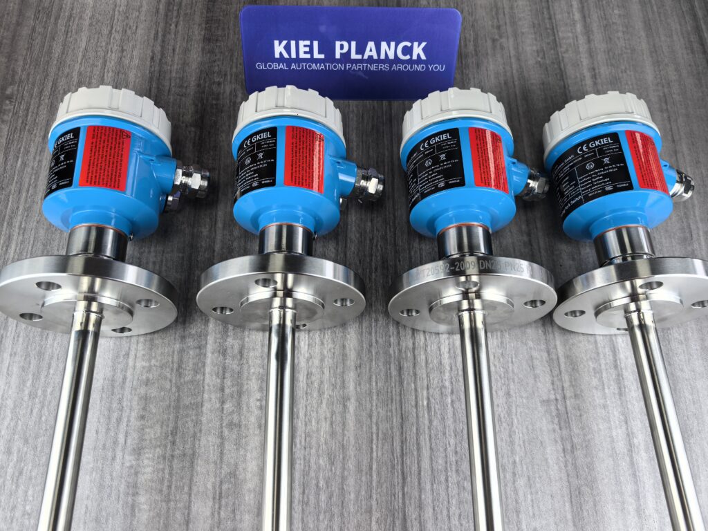
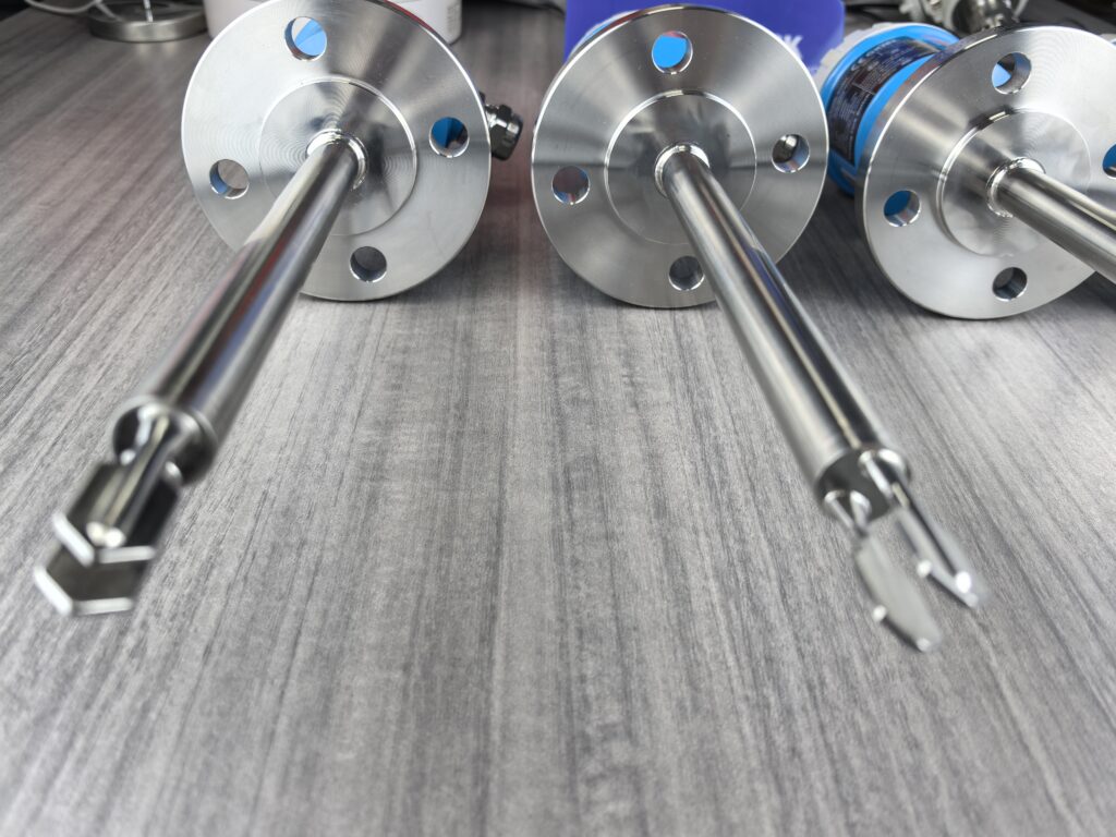
I. Importance and Principle of Capacitance Measurement
1. Why Capacitance is a Key Parameter
The static capacitance of piezoelectric ceramics is a core indicator of their performance. It reflects not only the dielectric properties of the ceramic but is also directly affected by factors such as material properties, geometry, thickness, and surface area. In tuning fork level switches, the piezoelectric ceramic is responsible for driving the tuning fork probe to vibrate and detecting changes in vibration state. The stability of its capacitance directly affects:
Driving efficiency: Abnormal capacitance can lead to weak vibration or even no vibration at all.
Detection sensitivity: Affects the conversion efficiency of weak vibration signals.
Product consistency: Discrepancies in capacitance values within the same batch of products can lead to performance differences.
Long-term reliability: Increased capacitance after use is a common cause of malfunctions.
2. Difference between Static and Dynamic Capacitance
Static capacitance: Refers to the capacitance of the piezoelectric ceramic in a non-vibrating state. It is mainly determined by the dielectric constant and geometric dimensions of the material and is a key parameter for quality control.
Dynamic capacitance: Refers to the equivalent capacitance under operating conditions (vibration). It is affected by vibration frequency, amplitude, and dielectric damping, and is fundamentally different from static capacitance.
Capacitance Measurement Procedure
Preparation: Set the LCR bridge to 1kHz frequency, C-D test mode, and perform open/short circuit calibration.
Jig Installation: Place the piezoelectric ceramic sheet to be measured between the copper plates of the fixture, and connect the electrodes at both ends of the fixture using the dedicated bridge chuck.
Measurement Operation:
Start the LCR bridge for measurement.
Wait 10-30 seconds for the reading to stabilize, then record the result.
For jump data, record the last two digits (MAX and minimum jump values), and take the average as the final measurement result.
Quality Judgment: The capacitance value should be within the range specified in the specification. Generally, the capacitance value deviation within the same batch of products is required to be within ±3%.
3. Impact of Fixture Design on Measurement Stability
Traditional clamping methods easily introduce stress interference, leading to unstable measurement results. Dedicated fixtures use highly conductive copper plates and insulating supports, effectively avoiding capacitance changes under pressure and stress, and improving measurement repeatability.
Precautions during measurement:
Avoid direct contact of fingers with the ceramic surface to prevent moisture absorption.
In environments with high humidity, consider performing measurements in a drying oven.
Ensure the ceramic surface is clean and dry before measurement.
III. Capacitor Matching and Product Reliability
1. Capacitor Matching Requirements for Piezoelectric Ceramic Components
In a 6+1 piezoelectric ceramic component (6 driving elements + 1 sensing element), the capacitors of each element must be matched:
Driving element matching: The static capacitance values of the 6 driving piezoelectric ceramic elements should be within ±5% of each other.
Sensing element matching: The static capacitance of the sensing element should be as close as possible to the average value of the 6 driving elements.
Product consistency: The capacitance values of products in the same batch should be controlled within ±3% to ensure that the amplitude and sensitivity meet the design standards.
Capacitor mismatch will lead to:
Weak vibration or even no vibration of the vibration probe
Reduced signal-to-noise ratio of the detection signal
Poor product consistency, prone to malfunction in field applications
2. Relationship between Preload and Capacitance
During assembly, as the bolt tightening torque increases, the static capacitance of the piezoelectric ceramic element shows a trend of first decreasing and then increasing. To find the best preload, the static capacitance C0 should be measured before preload, and then the capacitance change should be monitored during preload. When the capacitance value reaches the range of (1 to 1.05)C0, it is the best preload state. Too little preload will result in insufficient driving force, while too much will affect vibration and easily cause the piezoelectric element to break.
IV. Practical Tips
Handling Measurement Fluctuations: In environments with high humidity and strong airflow, the piezoelectric ceramic surface easily absorbs moisture, leading to unstable readings. Wait until the reading fluctuation decreases to within ±3% before recording the value.
Issues with Domestic Piezoelectric Ceramics: Domestic products often suffer from an increase in static capacitance after a period of use. A new product might measure 1360pF, but after use it can reach 1490-1560pF, resulting in weak vibration and malfunctions.
Capacitor Screening Practice: In the Ring-11 tuning fork level switch, high-precision capacitance screening (within ±3%) significantly improves the reliability of the equipment in measuring low-density materials.
Regular Calibration: It is recommended to calibrate the measurement system every 3-6 months, including the LCR bridge and dedicated fixtures, to ensure measurement accuracy.
Alternative Solution Considerations: In high-viscosity, easily adhered material conditions, if the piezoelectric ceramic capacitance matching is insufficient, an RF admittance level switch can be considered as an alternative.
Although piezoelectric ceramic capacitance measurement is a minor detail, it determines the performance ceiling of tuning fork level switches. Standardized measurement procedures and rigorous quality control can effectively improve product consistency and long-term reliability, especially in applications involving low-density materials and complex operating conditions.
Please contact us promptly if needed.





