

Tuning fork level switches can have their service life significantly extended through scientific selection, standardized installation, regular maintenance, and targeted optimization. Especially in complex working conditions such as easy crystallization, high vibration, and strong corrosion, reasonable usage strategies can effectively prevent failures and ensure long-term stable operation of the equipment.
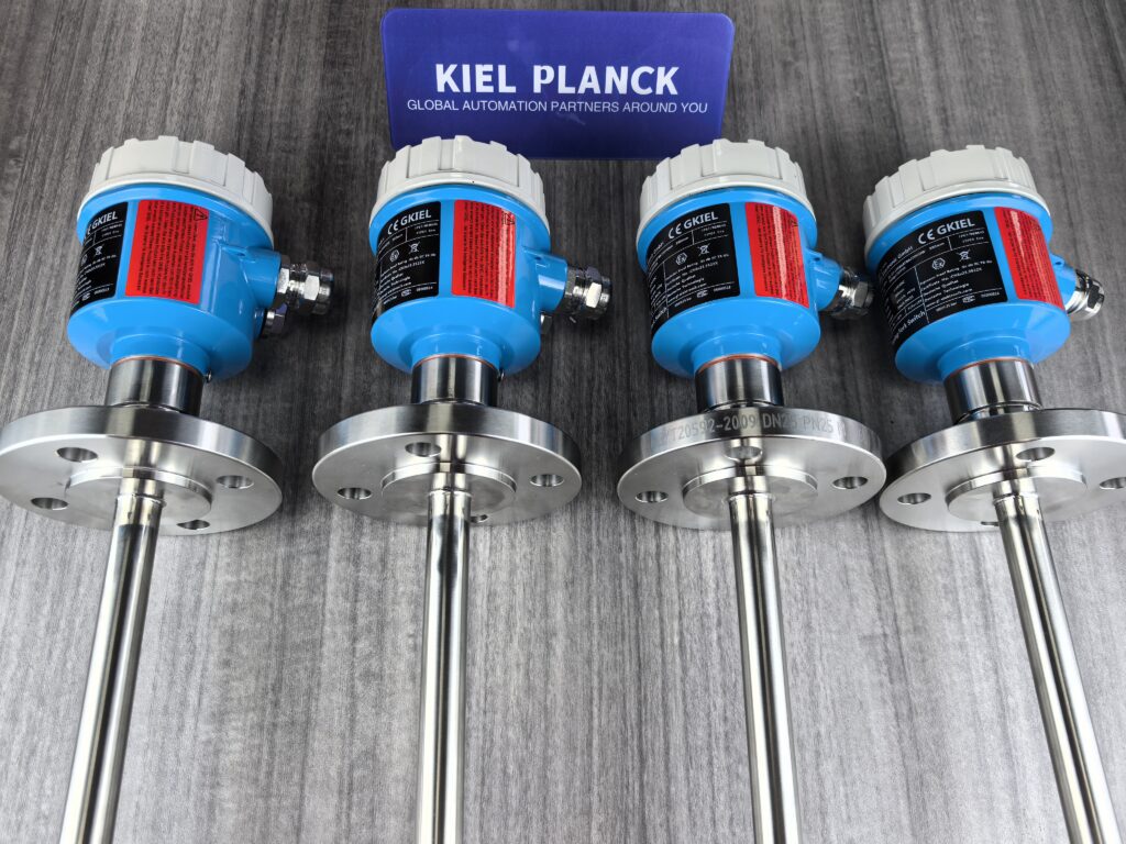
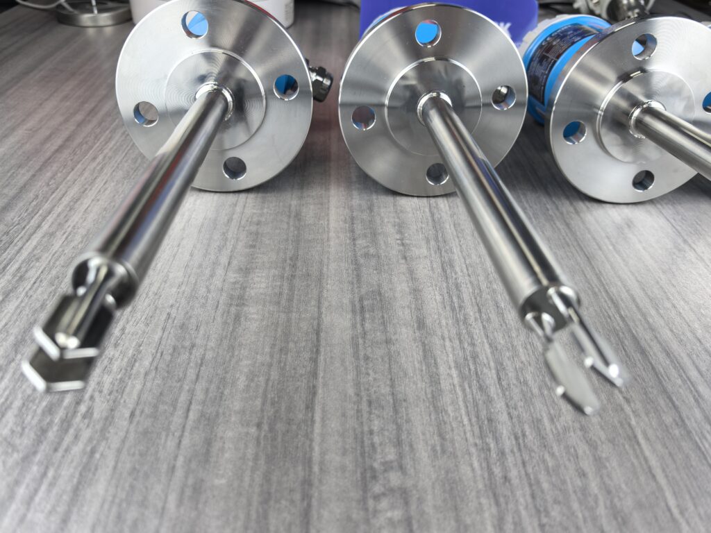
I. Correct Selection and Installation: The Foundation for Extended Lifespan
1. Precise Matching to Operating Conditions
Material Selection: For corrosive media (such as nickel sulfate solution), prioritize corrosion-resistant materials such as 316L stainless steel and Hastelloy to prevent rapid failure of carbon steel in corrosive environments.
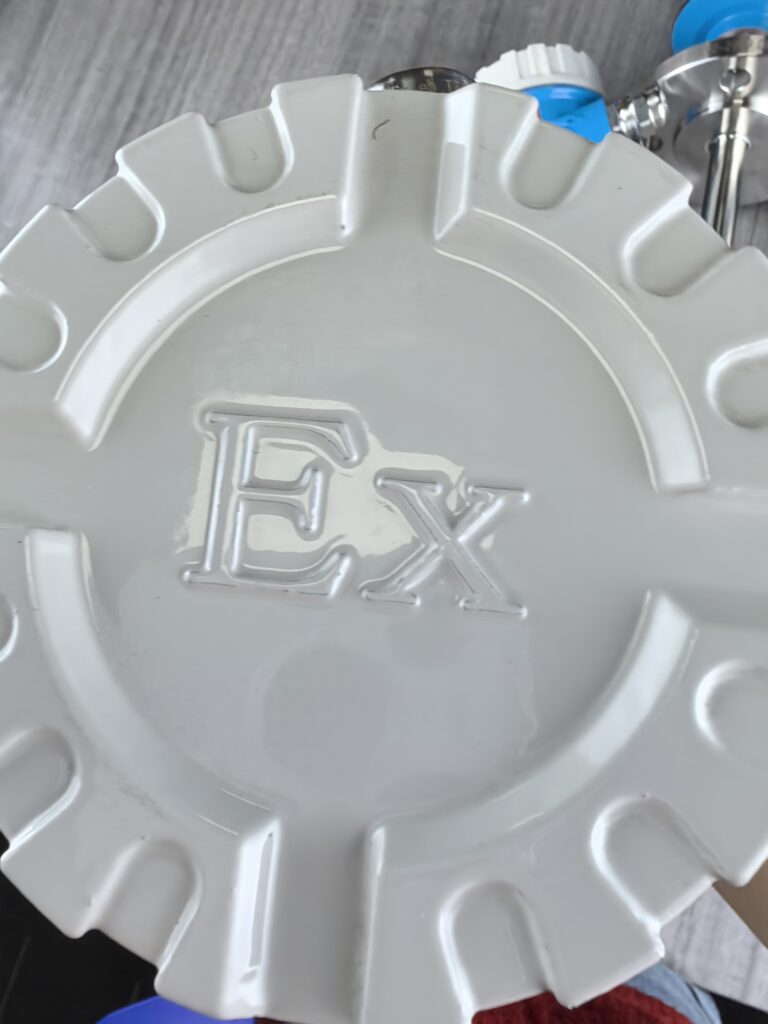
Explosion-proof and Protection: In flammable and explosive environments, products meeting explosion-proof certifications such as Ex d IIC T6 Gb must be selected; for outdoor installations, a high protection rating of IP67/IP68 is required.
Special Functions: For easily crystallizing media (such as syrups and salt solutions), choose models with “anti-crystallization” or “self-cleaning” functions. These products effectively prevent crystal accumulation through specially designed smooth spherical tips and automatic strong vibration modes.
2. Standardized Installation and Operation
Location Selection: The installation location should avoid the feed inlet, agitator, and liquid impact areas to prevent direct impact from materials that could deform or damage the fork teeth.
Installation Direction: The fork body surface should be aligned with the direction of liquid rise or flow to avoid measurement errors caused by the resistance of the medium to the fork body.
Moisture-proof measures: When installed outdoors, the cable should be bent and run downwards to prevent rainwater and condensation from entering the instrument.
II. Routine Maintenance and Care: Key to Extending Lifespan
1. Regular Inspection and Cleaning Schedule
Inspection Frequency: Develop an inspection schedule based on the characteristics of the medium. For media prone to crystallization (such as salt solutions and syrups), weekly inspection is recommended; for clean media, monthly inspection is sufficient.
Cleaning Method: When crystals or deposits are found, stop the machine and gently soak and wipe with a soft cloth, warm water, or a suitable solvent. Do not use hard objects to scrape, as this may damage the fork teeth.
Heavy Contamination Treatment: For viscous, oily substances, gently scrape off the surface solidification with a soft bamboo stick or plastic scraper, then repeatedly wipe with a cloth dampened with neutral detergent.
2. Calibration and Functional Testing
Regular Calibration: It is recommended to perform calibration every 3-6 months, including zero-point calibration and full-scale calibration, to ensure measurement accuracy.
Functional Testing: Simple functional tests can be used to check if the switches are functioning properly. For example, slowly immerse the tuning fork level switch’s fork body in water and observe whether it correctly triggers the signal upon contact with the liquid (usually manifested as a change in indicator light status and relay activation), and whether it resets promptly after being removed from the liquid.
III. Special Operating Condition Coping Strategies: Targeted Lifespan Extension
1. Crystallization and Adhesion Issues
Prevention Measures: Choose a suitable installation location, avoiding placing the tuning fork switch in dead corners prone to sedimentation and crystallization; fine-tuning the installation angle can sometimes effectively reduce crystal adhesion.
Self-Cleaning Function: Activating the “self-cleaning” function uses high-frequency vibration to shake off adhering substances, especially suitable for easily crystallizing materials (such as syrups and salt solutions).
2. High Vibration Environments
Vibration-Resistant Design: In high vibration environments, select products optimized through modal testing and finite element analysis (FeA) to ensure their natural frequencies avoid the pump vibration frequency band, effectively suppressing high-frequency noise propagation within the fork body.
Installation Optimization: During installation, ensure the tuning fork level switch’s installation direction aligns with the liquid flow direction to reduce the impact of vibration on measurement.
3. High Viscosity and Easily Adhesive Media
Installation Method Optimization: When the measured medium is viscous, to reduce or avoid material adhesion, the instrument should be installed vertically.
Alternative solution: In environments with high viscosity, easy material adhesion, and strong stirring, if conditions do not permit, an RF admittance level switch can be considered as an alternative solution.
IV. Practical Tips and Maintenance Plan Examples Practical Tips
Avoid contact with hard objects: During installation and maintenance, never grasp the fork probe with your hands or strike it with hard objects to avoid deformation of the fork probe or damage to the internal piezoelectric components.
Protect seals: Seals must be completely dry after cleaning before installation to prevent moisture residue from causing mold or media mixing.
Regular record keeping: Establish maintenance records, including cleaning time, crystallization status, calibration data, etc., to help predict maintenance cycles.
Maintenance Plan Example
Please contact us promptly if needed.





