

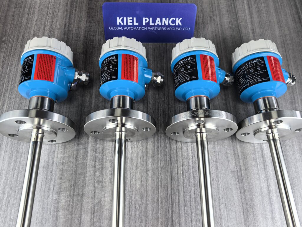
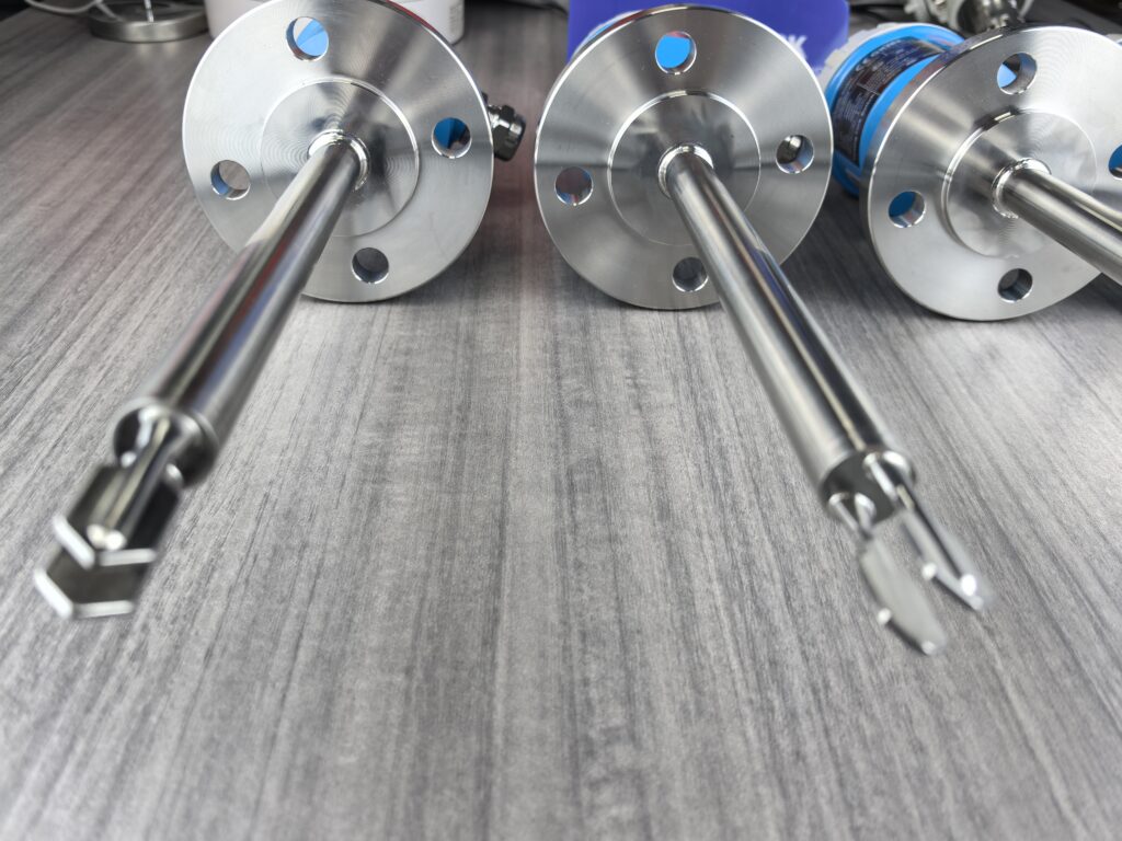
Tuning fork level switches determine the liquid level by detecting changes in the vibration frequency of the tuning fork. When liquid comes into contact with the tuning fork, its vibration frequency and amplitude change significantly due to damping. The intelligent circuit detects this change and triggers a switch signal, thereby achieving accurate monitoring of the liquid level.
I. Pre-installation Preparation
1. Verify Instrument Suitability
Verify that the instrument model meets the site environment requirements, including process pressure, process temperature, and the chemical properties of the medium.
Check the integrity of the packaging and confirm that all accessories are complete, such as power cord and instruction manual.
Prepare necessary tools: adjustable wrench (compatible with thread specifications such as G1/2, G3/4), box wrench (for flange bolts such as M8/M10), etc.
II. Correct Installation Steps
1. Installation Location Selection
Avoid Interference Areas: Keep away from areas prone to impact or eddies, such as the inlet, agitator, and pump outlet, to prevent false alarms caused by violent media fluctuations.
Maintain a distance of at least 30cm from the inlet to avoid damage or false alarms caused by material impact.
If the container has an agitator, the distance between the tuning fork and the agitator should be ≥1.5 times the agitator radius.
Select a Dynamic Liquid Level Monitoring Point: Prioritize areas with gradual liquid level changes that represent the overall liquid level, such as the middle section of the container side wall or a vertical installation position at the top.
Confirm No Blind Spots:
High Liquid Level: The bottom of the tuning fork should be 50mm below the liquid level line.
Low Liquid Level: The top of the tuning fork should be 30mm above the liquid level line.
Allow ≥100mm of space to be left at the bottom of the container.
2. Installation Direction and Angle
Vertical Installation (Liquid): The tuning fork must be perpendicular to the liquid surface to ensure uniform vibration upon contact with the medium, reducing measurement errors.
Use the small dot at the threaded connection to determine the direction; upward/downward indicates correct (ensure it is upward or downward).
For viscous media, install at a 20° downward tilt to reduce material buildup.
Inclined Installation (Solid Particles): For powdery or granular media, tilt downward 15°-30° to prevent material accumulation on the fork surface.
Adjusting the Fork Direction: Align the fork surface with the direction of medium flow or agitator rotation to reduce the impact of fluid resistance on measurement.
3. Installation and Fixing Methods
Threaded Connection: Suitable for small containers or pipes. Direct fixation via external or internal thread interfaces. Ensure thread sealing.
Flanged Connection: Suitable for large storage tanks or high-pressure environments. Connects to the container via a flange. Verify flange specifications (e.g., DN25, DN50) and pressure rating (e.g., PN16, PN40).
Bracket Fixing: In scenarios where direct installation is not possible, use a bracket to fix the tuning fork level gauge to the outer wall of the container. Ensure bracket stability.
Protective Baffle: If the medium flows rapidly or contains abrasive particles, install a baffle above the vibrator with a length greater than the insertion length.
General Materials: Install a flat baffle with a length exceeding the insertion length.
Abrasive Materials: Use a concave baffle to buffer impact through material accumulation.
4. Electrical Connections and Wiring
Wiring Specifications:
Connect the power supply (24VDC or 220VAC), signal output (relay contacts or 4-20mA), and grounding wire according to the equipment manual.
The cable cross-sectional diameter should be 5-9mm; otherwise, the sealing effect at the cable inlet cannot be guaranteed.
The junction box inlet must face downwards, and the fixing nut at the power cable inlet must be tightened.
Wiring Steps:
Open the outer casing.
Loosen the locking nut on the cable thread connector.
Remove approximately 10cm of the outer sheath and approximately 1cm of insulation from the end of the core wire of the connecting cable.
Pass the cable through the cable thread connector and insert it into the casing.
Use a screwdriver to open the terminal block and insert the
I. Working Principle and Core Mechanism
The tuning fork level switch operates based on the principle of resonant frequency change. Its core mechanism can be summarized as follows:
Vibration Excitation: A pair of piezoelectric crystals mounted on the tuning fork base induce stable resonant vibration at a specific frequency (typically 280-350Hz).
Media Detection: When the liquid level rises to submerge the tuning fork, the density and viscosity of the liquid dampen the vibration, causing a significant decrease in the vibration frequency (typically 10%-30%).
Signal Conversion: The electronic control unit monitors the vibration frequency in real time. When the frequency drops to a preset threshold, it determines that the “liquid level has been reached,” triggering a relay to output a switching signal.
The core advantage of the tuning fork level switch lies in its detection principle, which is based on frequency change. Therefore, it is unaffected by interference factors such as medium electrical parameters, density, scaling, agitation, turbulence, bubbles, and vibration, maintaining high reliability even under complex operating conditions.
II. Common Fault Analysis and Troubleshooting
1. Malfunction (Frequent Alarms)
Fault Phenomenon: Alarm signals are frequently triggered even though the liquid level has not reached the target level.
Main Causes:
The pipe or spray nozzle is directly hitting the tuning fork, causing the liquid to briefly sweep across the tuning fork and alter its vibration state.
The liquid is violently fluctuating, churning, or causing interference from a large amount of foam/bubbles.
Improper installation location, such as being near the inlet or agitator.
Troubleshooting Methods:
1. Adjust the installation position to ensure the tuning fork is away from the feed inlet, agitator, and other sources of interference.
For foam or bubble issues, consider using a tuning fork structure optimized for complex operating conditions (such as Ring-11), which is more adaptable to foam and bubbles.
Check and clean any deposits on the tuning fork surface to ensure its vibration is unimpeded.
2. No Action (No Signal Output)
Symptom: Liquid level reached but no alarm signal.
Main Causes:
Scale or deposits on the tuning fork surface, affecting the vibration frequency.
Insufficient damping of the tuning fork vibration by low-density liquids or special media (such as LNG, high-pressure liquefied gas).
Electronic component failure or power supply problem.
Improper installation position, tuning fork not effectively in contact with the liquid.
Troubleshooting Methods:
Clean the tuning fork regularly to prevent deposits or scale from affecting vibration.
For low-density liquids, choose a tuning fork level switch specifically designed for such media, capable of detecting densities as low as 0.5. Liquid g/cm³
Check power supply for proper function; test excitation and detection circuits.
Confirm correct installation location and that the tuning fork is within the effective range of liquid level change.
3. Unstable Signal (Repeated Fluctuations)
Symptom: Output signal frequently switches and is unstable.
Main Causes:
Frequent liquid fluctuations cause unstable vibration of the tuning fork.
The tuning fork is partially covered by liquid, in an “intermediate state,” such as within a foam layer.
Circuit interference or poor connections.
Solutions:
Optimize installation location, avoiding areas of severe liquid fluctuation.
For conditions with a large amount of foam, consider using a tuning fork level switch optimized for complex conditions, which is more adaptable to foam.
Check and tighten all electrical connections, eliminating poor contact.
Adjust sensitivity and response time parameters to better adapt the equipment to actual operating conditions.
Installation Direction: The tuning fork body should be parallel to the direction of liquid rise or flow to avoid interference from the liquid flow direction.
Regular Inspection: It is recommended to check the tuning fork surface for scale buildup monthly and perform a functional test quarterly.
High/Low Mode: The high/low mode should be adjusted according to actual operating conditions to ensure the level switch triggers an alarm or control signal at a specific liquid level.
Alternative Solutions: In high-viscosity, easily deposited, or strongly agitated environments, radio frequency admittance level switches or radar level gauges can be considered as alternatives.
Although tuning fork level switches are simple in structure and maintenance-free, they still require targeted selection and regular maintenance under complex operating conditions. Understanding their working principle and failure mechanisms can help engineers mitigate risks during the selection phase and ensure long-term stable operation.
Please contact us promptly if needed.





