

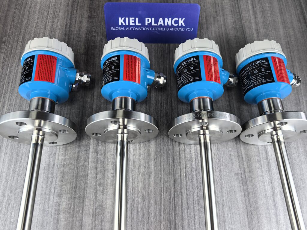
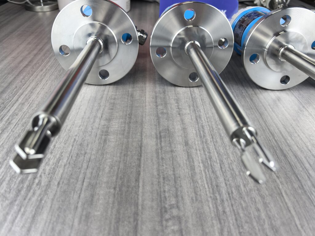
Proper installation and use of tuning fork level switches require selecting a suitable installation location, ensuring the correct installation direction, and performing appropriate debugging and maintenance to guarantee measurement accuracy and long-term stable operation of the equipment.
I. Pre-installation Preparation
1. Verify Instrument Suitability
Verify that the instrument model meets the site environment requirements, including process pressure, process temperature, and the chemical properties of the medium.
Check the integrity of the packaging and confirm that all accessories are complete, such as power cord and instruction manual.
Prepare necessary tools: adjustable wrench (compatible with thread specifications such as G1/2, G3/4), box wrench (for flange bolts such as M8/M10), etc.
II. Correct Installation Steps
1. Installation Location Selection
Avoid Interference Areas: Keep away from areas prone to impact or eddies, such as the inlet, agitator, and pump outlet, to prevent false alarms caused by violent media fluctuations.
Maintain a distance of at least 30cm from the inlet to avoid damage or false alarms caused by material impact.
If the container has an agitator, the distance between the tuning fork and the agitator should be ≥1.5 times the agitator radius.
Select a Dynamic Liquid Level Monitoring Point: Prioritize areas with gradual liquid level changes that represent the overall liquid level, such as the middle section of the container side wall or a vertical installation position at the top.
Confirm No Blind Spots:
High Liquid Level: The bottom of the tuning fork should be 50mm below the liquid level line.
Low Liquid Level: The top of the tuning fork should be 30mm above the liquid level line.
Allow ≥100mm of space to be left at the bottom of the container.
2. Installation Direction and Angle
Vertical Installation (Liquid): The tuning fork must be perpendicular to the liquid surface to ensure uniform vibration upon contact with the medium, reducing measurement errors.
Use the small dot at the threaded connection to determine the direction; upward/downward indicates correct (ensure it is upward or downward).
For viscous media, install at a 20° downward tilt to reduce material buildup.
Inclined Installation (Solid Particles): For powdery or granular media, tilt downward 15°-30° to prevent material accumulation on the fork surface.
Adjusting the Fork Direction: Align the fork surface with the direction of medium flow or agitator rotation to reduce the impact of fluid resistance on measurement.
3. Installation and Fixing Methods
Threaded Connection: Suitable for small containers or pipes. Direct fixation via external or internal thread interfaces. Ensure thread sealing.
Flanged Connection: Suitable for large storage tanks or high-pressure environments. Connects to the container via a flange. Verify flange specifications (e.g., DN25, DN50) and pressure rating (e.g., PN16, PN40).
Bracket Fixing: In scenarios where direct installation is not possible, use a bracket to fix the tuning fork level gauge to the outer wall of the container. Ensure bracket stability.
Protective Baffle: If the medium flows rapidly or contains abrasive particles, install a baffle above the vibrator with a length greater than the insertion length.
General Materials: Install a flat baffle with a length exceeding the insertion length.
Abrasive Materials: Use a concave baffle to buffer impact through material accumulation.
4. Electrical Connections and Wiring
Wiring Specifications:
Connect the power supply (24VDC or 220VAC), signal output (relay contacts or 4-20mA), and grounding wire according to the equipment manual.
The cable cross-sectional diameter should be 5-9mm; otherwise, the sealing effect at the cable inlet cannot be guaranteed.
The junction box inlet must face downwards, and the fixing nut at the power cable inlet must be tightened.
Wiring Steps:
Open the outer casing.
Loosen the locking nut on the cable thread connector.
Remove approximately 10cm of the outer sheath and approximately 1cm of insulation from the end of the core wire of the connecting cable.
Pass the cable through the cable thread connector and insert it into the casing.
Use a screwdriver to open the terminal block and insert the end of the core wire according to the wiring diagram.
Tighten the terminal block and check that the connection is secure.
Tighten the locking nut on the cable thread connector and fasten the sealing ring.
Tighten the outer casing.
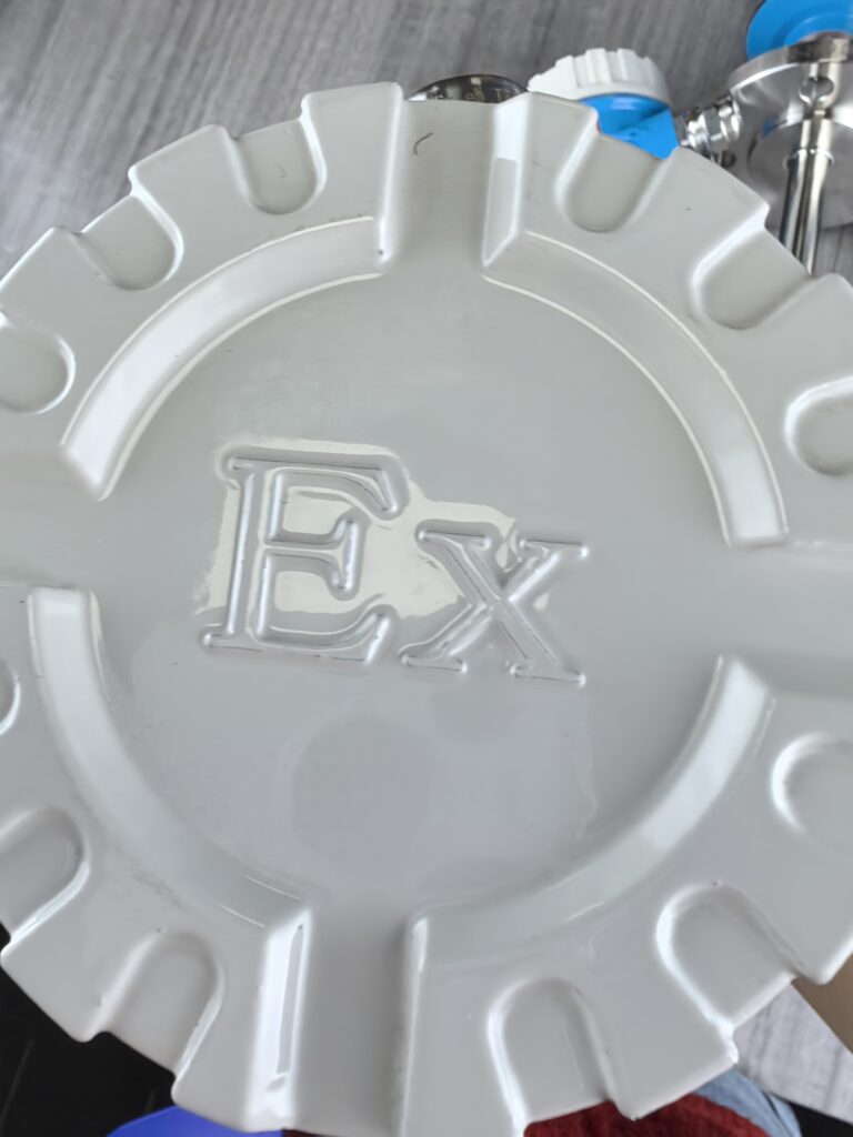
Safety Notes: Wiring should only be performed when the power is off; for explosion-proof instruments, opening the outer casing is only permitted when there is no explosive gas or dust in the environment.
5. Moisture-proofing and Sealing Measures
For outdoor installation, the junction box should face downwards, and the cable should be bent downwards to prevent rainwater ingress.
Moisture-proof installation: Ensure the cable is bent downwards to prevent moisture from entering.
Sealing check: Ensure there are no leaks at flange or threaded connections; use gaskets or sealant if necessary.
Explosion-proof type: Additional space for heat dissipation is required; spacing ≥ 80mm.
III. Post-Installation Commissioning and Use
1. Sensitivity Calibration
Adjusting Sensitivity: Adjust the sensitivity knob or parameter settings to ensure the device accurately outputs a signal at the target liquid level.
For example: Set the high liquid level alarm threshold to a 10% decrease in the tuning fork vibration frequency.
For viscous media, the sensitivity can be appropriately increased to reduce the impact of material buildup.
Density Switch: Tuning fork level switches are usually equipped with a density switch to adjust the sensitivity according to the density of the measured material.
The higher the material density, the lower the required sensitivity.
The lower the material density, the higher the required sensitivity.
2. Functional Testing
Simulating Liquid Level Changes: For example, adding water or discharging material, observe whether the output signal matches the actual liquid level. Adjust parameters if necessary.
Testing Method: Lift the tuning fork and vertically insert it into the water to a depth greater than 30mm. At this time, the output indicator light will illuminate and the relay will engage. Then lift the tuning fork out of the water surface; the output indicator light will turn off, and the relay will release, indicating normal operation.
3. High/Low Level Mode Settings
High/Low Level Mode Switching: The high/low level mode (High/Low) switch on the instrument needs to be adjusted according to the actual site requirements.
High Level Mode: Alarm occurs when the liquid level reaches the set height.
Low Level Mode: Alarm occurs when the liquid level is below the set height.
DIP Switch: Pushing it up activates high level mode, and pushing it down activates low level mode. The factory default setting is usually high level mode.
IV. Usage Precautions and Maintenance
1. Daily Usage Precautions
Avoid Inverted Installation: Tuning fork level switches must not be installed with the fork tip facing upwards.
Avoid Installation at the Inlet: If unavoidable, a partition must be installed between the inlet and the level gauge for protection.
Viscous Media: Vertical installation is recommended, with the spacing reduced to 30mm, but ensure no material adheres to the fork.
High-Temperature Conditions: Allow for thermal expansion clearance (e.g., 0.5-1mm expansion for a 40mm fork).
2. Regular Maintenance
Clean Tuning Fork Surface: Regularly remove surface deposits to ensure accurate detection.
Check Connection Cables: Check for tightness and damage to the cables.
Check Protective Baffle: High temperatures may deform the baffle; use high-temperature resistant materials (e.g., 316L stainless steel) and check regularly.
Regular Calibration: To ensure the accuracy and reliability of the tuning fork level switch, regular calibration is necessary.
3. Troubleshooting Common Issues
Abnormal Vibration Frequency: Check circuit connections for proper functioning; repair or replace damaged components.
False Alarms: Adjust sensitivity settings or install filters to reduce interference.
Power Supply Issues: Check power lines and ensure a stable power supply.
Mechanical Damage: Regularly check equipment operation and replace worn parts promptly.
V. Special Operating Condition Handling
1. High-Temperature Environment
Thermal Expansion Factors: High temperatures may cause the fork to expand; a thermal expansion gap must be allowed.
Media Characteristics: High temperatures may change the viscosity of the medium; the installation angle needs to be adjusted (e.g., tilted downwards by 20°).
Protective Baffle: High-temperature resistant materials (e.g., 316L stainless steel) must be selected and inspected regularly.
2. Easily Crystallizing Media
Avoid Crystallization Areas: The installation location should be chosen on the side wall or top of the container where the medium is not prone to crystallization.
Vertical Installation: Vertical installation is recommended to reduce the accumulation of crystals on the fork.
Add a Purge Device: Install a purge device on the tuning fork level switch to regularly remove crystals.
Regular Maintenance: Regularly inspect the fork surface and clean crystals promptly to avoid false alarms.
3. Installation of Atmospheric Pressure Vessels
Avoid Material Disturbance Sources: Maintain a horizontal distance ≥ 3 times the length of the tuning fork to prevent material impact from causing false triggering.
Reserve Maintenance Space: A minimum of 500mm of operating space (radius) must be reserved around the tuning fork.
Atmospheric Pressure Compatibility: No high-pressure seals are required. Prepare tools and accessories that are easy to install, leak-proof, and corrosion-resistant.
By following the above steps and precautions, you can ensure the correct installation and use of the tuning fork level switch, improving measurement accuracy and equipment lifespan. Strict adherence to installation specifications, regular maintenance, and calibration are crucial for ensuring the long-term stable operation of the tuning fork level switch.
Please contact us promptly if needed.





