

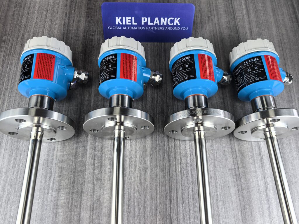
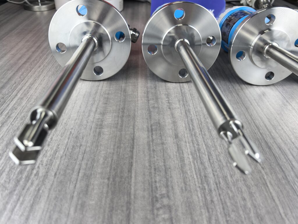
The vibration frequency design of the tuning fork level switch is based on physical parameter calculations. By adjusting the length, thickness, and material of the tuning fork, the frequency can be finely adjusted to adapt to different media characteristics and operating conditions, thereby ensuring the accuracy and reliability of the detection.
I. Vibration Frequency Design Principle and Calculation
The vibration frequency of a tuning fork level switch is a core parameter for its operation, and it is typically designed within the range of 100–1000 Hz. Its nominal resonant frequency can be calculated using the following empirical formula:
f=0.161Egρ⋅tL²
Where:
LL: Fork length (m)
tt: Fork thickness (m)
EE: Young’s modulus (kgf/m²)
gg: Acceleration due to gravity (980cm/s²)
ρρ: Fork material density (kg/m³)
This formula indicates:
Fork length: The vibration frequency is inversely proportional to the square of the fork length; the longer the fork, the lower the frequency.
Fork thickness: The vibration frequency is directly proportional to the thickness; the thinner the fork, the lower the frequency.
Material properties: The higher the Young’s modulus (the stronger the material rigidity), the higher the frequency; the higher the density, the lower the frequency.
In practical applications, when a liquid comes into contact with the tuning fork, its vibration frequency will decrease significantly due to damping (usually by 10% to 30%). This change is used to determine the liquid level.
Electronic Parameter Adjustment
Modern tuning fork level switches are typically equipped with intelligent detection circuits, allowing for fine-tuning in the following ways:
Drive Frequency Adjustment: Dynamically adjusts the frequency of the driving electric field through phase difference detection and negative feedback closed-loop to compensate for frequency shifts caused by environmental factors.
Gain Adjustment: Automatically optimizes the signal amplification factor for media of different densities. For example, the gain coefficient is 1.2 when measuring water (density 1.0 g/cm³), but adjusted to 0.8 when measuring polyethylene powder (density 0.92 g/cm³).
Digital Filtering: Uses filters, notch filters, and other tools to process the vibration signal, improving the signal-to-noise ratio.
III. Frequency Selection Strategies for Different Operating Conditions
1. Frequency Differences Between Liquids and Solids
Liquid Detection: Typically uses higher frequencies (e.g., 280-350Hz), capable of detecting liquids with densities as low as 0.5 g/cm³.
Solid Detection: Typically uses lower frequencies, capable of detecting particles/powders with densities as low as 0.008 g/cm³.
Note: Universal tuning fork switches for both solids and liquids often have limited density adaptability and poor stability. It is recommended to select a dedicated model based on the actual medium.
2. Influence of Medium Characteristics on Frequency
Low-viscosity liquids (e.g., water, oil): Frequency and amplitude decrease significantly, but the tuning fork can still vibrate normally.
High-viscosity liquids (e.g., syrup, asphalt): May cause the tuning fork to fail to oscillate properly; a low-frequency design is required.
Particles/Powders: Tuning fork vibration is rapidly constrained or even stops; a design sensitive to amplitude changes is required.
3. Environmental Factor Compensation
Temperature Change: The built-in thermistor monitors the ambient temperature in real time, and the influence of temperature on the piezoelectric crystal parameters is corrected using a lookup table method.
Pressure Change: In high-pressure environments (e.g., 40 bar), the effect of probe deformation on the frequency needs to be considered.
Foam Interference: The true liquid level and foam boundary are distinguished through frequency change pattern recognition (rather than simple amplitude detection).
IV. Practical Tips
Selection Recommendation: For liquids with a density ≥ 0.7 g/cm³, a standard tuning fork level switch is sufficient; for liquids with a density between 0.5-0.7 g/cm³, a model specifically designed for low-density liquids should be selected.
Installation Direction: The fork surface should be aligned with the direction of liquid rise or flow to avoid measurement errors caused by the resistance of the medium to the fork.
Sensitivity Adjustment: Some tuning fork level switches are equipped with a sensitivity adjustment switch, which can be adjusted according to the density of the measured medium. For example, when measuring the density of a liquid greater than or equal to 0.7 g/cm³, the density switch is usually turned to the down position; while when measuring liquids with lower densities, the density switch can be turned to the high-end position to improve sensitivity.
Avoid these misconceptions: Higher frequency is not always better. While higher frequencies are more sensitive to liquid level changes, they also increase the difficulty of resonance and manufacturing costs. A trade-off must be made based on actual needs.
Maintenance Tips: Regularly check the tuning fork surface for scale buildup, as deposits can alter the effective mass of the fork, thus affecting its vibration frequency.
The design and fine-tuning of the vibration frequency of a tuning fork level switch is crucial for balancing detection sensitivity, stability, and applicability. Understanding its principles and making appropriate selections and adjustments based on actual operating conditions can significantly improve detection reliability and extend equipment lifespan.
Please contact us promptly if needed.





