

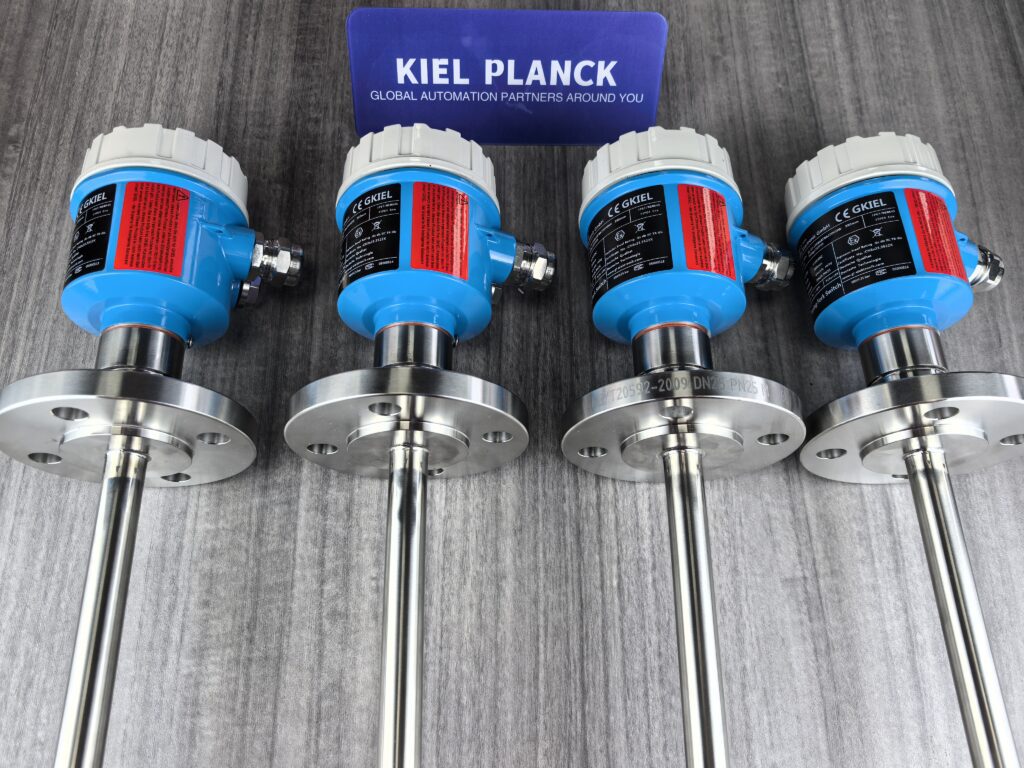
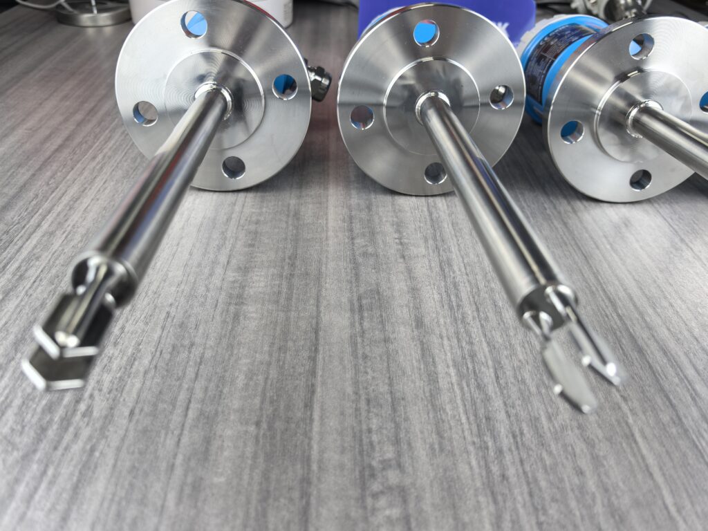
Tuning fork level switches determine the liquid level by detecting the difference in vibration frequency between the tuning fork in air and liquid. The core of the switch consists of a tuning fork probe, a piezoelectric crystal, and an electronic control unit. It has significant advantages such as simple structure, strong adaptability, and maintenance-free operation.
I. Detailed Explanation of Working Principle
1. Core Principle
The tuning fork level switch operates based on the principle of resonant frequency change. It determines the liquid level by detecting the difference in vibration characteristics of the tuning fork in different media. The specific process is as follows:
• Vibration Excitation Stage: The electronic control unit applies a fixed-frequency excitation (typically 100–1000 Hz) to the tuning fork via a piezoelectric crystal, causing the tuning fork to vibrate stably in the air at its natural resonant frequency.
• Medium Contact Stage: When the liquid level rises to submerge the tuning fork, the density of the liquid is much greater than that of air, which significantly dampens the vibration of the tuning fork, causing the vibration frequency to drop sharply (typically by 10%–30%).
• Signal Judgment Stage: The electronic control unit monitors the vibration frequency of the tuning fork in real time. When the frequency drops to a preset threshold (the characteristic frequency of the liquid environment), it determines that “the liquid level has been reached,” triggers the switch, and outputs an alarm or control signal.
• Reset Stage: When the liquid level drops and the tuning fork is exposed to air again, the vibration frequency returns to its natural value, the switch resets, and one detection cycle is completed.
2. Key Technical Features
• Frequency Change Mechanism: The vibration frequency change of a tuning fork in a liquid is mainly affected by the density and viscosity of the medium. The higher the density and viscosity, the more significant the frequency drop.
• Detection Sensitivity: Modern tuning fork level switches can detect liquid level changes of ±3mm, with a response time typically less than 1.5 seconds.
• Anti-interference Ability: Because the detection principle is based on frequency change rather than pressure or buoyancy, it is unaffected by interference factors such as foam, turbulence, bubbles, and vibration.
II. Core Structure and Components
1. Tuning Fork Probe (Vibrating Body)
• Shape and Material: Composed of two parallel metal forks, similar to a musical instrument tuning fork, with fork lengths typically ranging from several centimeters to over ten centimeters. Material selection based on media characteristics:
o Stainless steel 304/316: Suitable for general corrosive liquids
o Hastelloy: Suitable for highly corrosive media (such as hydrochloric acid, sodium hydroxide)
o Plastic: Suitable for mildly corrosive or food-grade applications
• Functional characteristics: As a vibration carrier, it is in direct contact with the medium, and its vibration state (frequency) changes with the surrounding medium.
2. Piezoelectric Crystal (Vibration Source and Sensor)
* Material and Principle: Utilizes a crystal with piezoelectric effect (such as quartz or ceramic piezoelectric elements), serving both driving and detection functions:
* **Inverse Piezoelectric Effect:** When an alternating voltage is applied, periodic mechanical deformation is generated, driving the tuning fork to vibrate.
* **Direct Piezoelectric Effect:** Vibration and compression generate electrical charges, converting mechanical vibration into an electrical signal.
* **Installation Location:** Typically glued or soldered to the base of the tuning fork probe. When the crystal expands and contracts, it drives the entire tuning fork to resonate.
3. Electronic Control Unit (Signal Processing Center)
* **Composition:** Contains electronic components such as circuit boards, chips, and relays, integrating signal generation, frequency detection, logic judgment, and output control functions.
• Core Functions:
o Outputs a stable excitation signal to the piezoelectric crystal.
o Acquires vibration frequency signals in real time and compares them with preset thresholds.
o When the frequency change reaches the trigger condition, it controls the relay to operate and outputs a switching signal.
4. Housing and Mounting Components
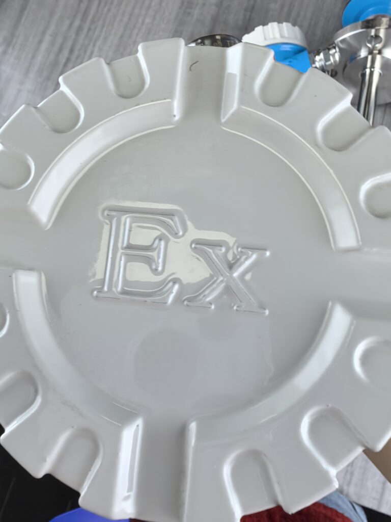
• Housing: Protects internal electronic components from environmental influences. Materials include plastic and metal, some with explosion-proof certification (e.g., Exd IIB T6 Gb).
• Mounting Interface: Typically threaded (e.g., G1/2, NPT1/2) or flanged, used to fix the tuning fork probe to container walls, pipes, etc., ensuring the fork extends vertically or horizontally into the detection area.
III. Types and Applications of Tuning Fork Level Switches
1. Main Types
* **Standard Tuning Fork Level Switch:** Suitable for general operating conditions; longer fork body, wide measuring range.
* **Compact Tuning Fork Level Switch:** Smaller fork body, particularly suitable for level measurement in pipelines and confined spaces; process temperature up to 150℃.
* **Special Material Type:** Such as Hastelloy tuning fork level switches, specifically designed for highly corrosive media environments, resistant to various strong acids, strong alkalis, and chloride media.
2. Typical Application Scenarios
* **Chemical Industry:** Level monitoring of highly corrosive media (hydrochloric acid, sodium hydroxide, etc.), and dry-run protection of pumps.
* **Food and Beverage Industry:** Monitoring the level of viscous liquids such as syrups, beer, and beverages; unaffected by viscosity.
* **Environmental Protection:** Monitoring the level of wastewater and slurry containing impurities in wastewater treatment systems; unaffected by foam and impurities.
* **Hazardous Locations:** In flammable and explosive environments (such as gasoline and liquefied gas storage), explosion-proof tuning fork level switches provide safety assurance.
IV. Technical Advantages and Maintenance Features
1. Key Advantages
* **High Adaptability:** Applicable to almost all liquid media (density ≥ 0.4 g/cm³) and free-flowing solid powders, unaffected by changes in media electrical parameters, density, viscosity, or temperature.
* **Maintenance-Free Design:** No moving parts, stable long-term operation, less prone to wear or jamming, significantly reducing downtime maintenance costs.
* **No Calibration Required:** No on-site calibration is required regardless of the medium being measured; it can be put into operation immediately after installation.
2. Maintenance and Troubleshooting
* **Common Faults:** No output signal, malfunction, unstable signal, etc., usually caused by power supply failure, improper installation location, or environmental interference.
* **Maintenance Recommendations:**
* **Regularly check the tuning fork surface for scale or deposits.**
* **Ensure the installation location is away from the feed inlet, agitator, and other sources of interference.**
* For high-viscosity liquids, the sensitivity setting can be adjusted appropriately.
Tune fork level switches, with their simple structure, reliable principle, and strong adaptability, have become the mainstream choice in the field of industrial liquid level monitoring. They are especially suitable for liquid level detection under complex working conditions, effectively replacing traditional float level switches and providing reliable technical support for industrial automation.
Please contact us promptly if needed.





