

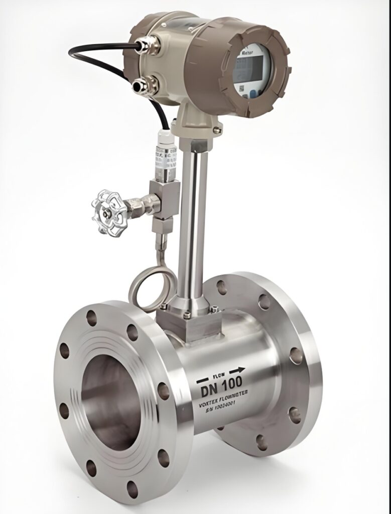
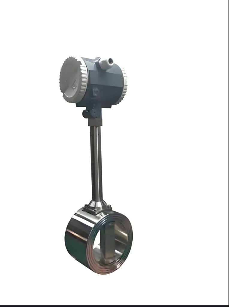
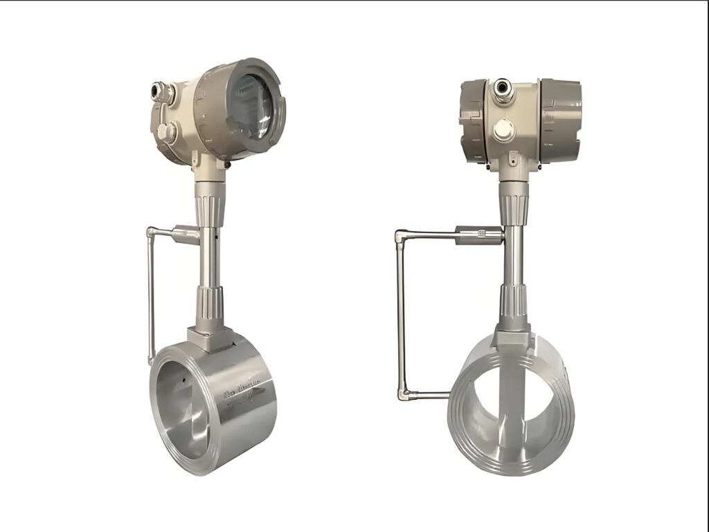
Vortex flow meters are widely used instruments in industrial flow measurement. Based on the Karman vortex street principle, they measure flow by detecting the frequency of vortices in the fluid. They have significant advantages such as no moving mechanical parts, wide range, and low pressure loss, and are suitable for flow measurement of various media such as gas, liquid, and steam.
I. Working Principle and Core Characteristics
1. Basic Working Principle
The core principle of a vortex flowmeter is the Karman vortex street phenomenon: when fluid flows at a sufficiently high velocity through a non-streamlined column perpendicular to the flow direction, a regular vortex pattern is generated alternately on both sides of the column. The vortex separation frequency is directly proportional to the fluid velocity and inversely proportional to the width of the column’s frontal surface. The mathematical expression is:
f = St × v / d
Where:
f: Vortex frequency (Hz)
St: Strowhal number (dimensionless constant, typically around 0.17)
v: Average fluid velocity (m/s)
d: Width of the column’s frontal surface (m)
By detecting the vortex frequency f, the fluid velocity v can be calculated, and thus the volumetric flow rate can be obtained.
2. Core Features
Advantages:
No moving parts, simple and robust structure, high reliability, low maintenance
Wide flow range: up to 1:15 for liquids, up to 1:30 for gases
Low pressure loss, approximately 1/2 to 1/4 that of orifice plate flowmeters
High measurement accuracy: ±1.0%R for liquids, ±1.5%R for gases/steam
Output is an electrical signal linearly related to flow rate, facilitating transmission and networking
Easy installation, wide range of pipe diameters (DN15-DN300)
Wide operating temperature range: -40℃ to +350℃
Limitations:
Sensitive to changes in flow velocity distribution and pulsating flow, affecting measurement accuracy.
Requires straight pipe sections upstream and downstream (typically 20D upstream and 5D downstream).
Contamination of the sensing element affects accuracy; regular cleaning is required.
Poor vibration resistance; vibration impact should be minimized.
Not suitable for low Reynolds numbers (<2×10⁴) or high viscosity fluids.
II. Applicable Media and Operating Conditions
1. Applicable Media Range
Gases: Compressed air, nitrogen, oxygen, natural gas, etc.
Liquids: Water, lubricating oil, light fuel oil, non-corrosive chemical liquids
Steam: Saturated steam, superheated steam
Special Note: Vortex flowmeters are not suitable for the following media:
Fluids containing a large amount of solid particles or suspended matter
High-viscosity oils (such as heavy oil)
Media with extremely low conductivity (unlike electromagnetic flowmeters, vortex flowmeters are not affected by conductivity)
Pulsating flow (such as fluids generated by Roots blowers or reciprocating pumps)
2. Operating Condition Requirements
Reynolds Number Range: Normal operating range is 2×10⁴~7×10⁶
Flow Rate Range:
Gas: 5~50m/s
Liquid: 0.5~7m/s
Steam: Requires determination based on temperature and pressure
Temperature Range:
Ambient Temperature: -25℃~100℃
Medium Temperature: -25℃~150℃
High Temperature: -25℃~250℃ (Some models can reach 350℃)
Pressure Range: 1.6MPa, 2.5MPa, 4.0MPa (depending on the model)
III. Key Points for Installation and Use
1. Installation Location Selection
Avoid the influence of high-power equipment, high-frequency equipment, and high-power switching power supplies.
Avoid direct influence from high-temperature heat sources and radiation sources.
Minimize vibration. If installation on vibrating pipes is necessary, install pipe fastening devices at 2D upstream and downstream.
Indoor installation is preferred. Outdoor installation requires proper waterproofing measures.
2. Pipe Installation Specifications
Straight pipe section requirements: Upstream 20D, downstream 5D (D is the pipe inner diameter)
Gas/Steam Measurement:
Vertical pipe installation is preferred, utilizing gravity to avoid fluid accumulation.
For horizontal installation, the pipe section must be elevated to create a natural drainage slope.
Liquid Measurement:
The pipe must be full. For vertical installation, the fluid should flow from bottom to top.
For horizontal installation with downward fluid flow, the downstream pipe must be elevated to create a liquid seal structure.
Mixed-phase flow is strictly prohibited: Vortex flow meters are only suitable for single-phase media (pure gas, pure liquid, pure steam).
3. Electrical Installation Requirements
Signal transmission lines should use shielded cables to prevent external induced noise.
Transmission cables must not be near strong electromagnetic equipment and must not be laid parallel to power lines.
Flow meters and transmitters must have reliable grounding; explosion-proof grounding wires must not be shared with the protective grounding of the high-voltage system.
At electrical interfaces, cables should be bent into a U-shape to prevent water from entering the amplifier housing along the cable.
IV. Maintenance and Troubleshooting
1. Key Points of Regular Maintenance
Monthly “Three Checks”:
First, check the output current: Observe whether there are abnormal fluctuations in the 4-20mA output.
Second, check the instrument coefficient: Compare with the initial calibration value to confirm whether the deviation is within the allowable range.
Third, check the process curve: Whether the flow fluctuation trend is consistent with the process changes.
Quarterly Inspections:
Probe Cleaning and Maintenance: Gently wipe away surface deposits with a soft cloth or special cleaning tool.
Sealing System Inspection: Check the flange sealing surface for signs of leakage.
Annual Maintenance:
Deep Probe Cleaning: Thoroughly remove stubborn dirt using a specialized cleaning agent.
Zero-Point Calibration: Perform zero-point calibration with the pipeline completely emptied.
Electrical System Testing: Conduct a comprehensive test of cable insulation resistance (should be >100MΩ).
2. Common Faults and Solutions
Flow in the pipeline, but the flow rate display shows 0:
Check if the low-flow cutoff value is set too high.
Check if the sensor is damaged or blocked by dirt.
Check if the amplifier is working properly.
No flow in the pipeline, but the displayed value is changing:
Check for external vibration interference.
Check if the grounding is good.
Check for electromagnetic interference.
Abnormal LCD display:
Check if the power supply is stable.
Check if the signal cable has good contact.
Check if the ambient temperature exceeds the operating range.
Unstable signal under low-flow conditions:
Early warning signal, indicating possible probe fouling.
It is recommended to schedule cleaning and maintenance immediately, rather than waiting for regular calibration.
V. Product Types and Selection Recommendations
1. Main Product Types
Integrated Vortex Flow Meter: Sensor and converter integrated, easy installation.
Intelligent Vortex Flow Meter: With temperature and pressure compensation function, it can measure mass flow rate.
Insertion Vortex Flow Meter: Suitable for large-diameter pipelines (DN150-DN2000)
Battery-Powered Type: Utilizes low-power technology; lithium battery power allows operation for more than one year.
Integrated Temperature and Pressure Compensated Type: Equipped with temperature/pressure sensors, it can measure standard condition volumetric flow rate and mass flow rate.
2. Key Considerations for Selection
Flow Rate Range: The commonly used flow rate should be controlled within the upper-middle range of the vortex shear’s measurable range.
Pipe Diameter: Select according to the actual pipe size, avoiding excessive reduction or expansion.
Media Characteristics: Clearly define the media type, temperature, pressure, viscosity, and other parameters.
Accuracy Requirements: Select an appropriate accuracy class (1.0, 1.5) based on process requirements.
Installation Environment: Consider environmental factors such as temperature, humidity, vibration, and explosion protection.
Output Signal: Select a suitable output method (pulse, 4-20mA, HART, etc.).
VI. Advanced Applications and Technological Development
1. Temperature and Pressure Compensation Technology
Integrated temperature and pressure compensation vortex flowmeters can directly measure the temperature and pressure of gaseous media, thereby displaying the standard volumetric flow rate of the gas.
For saturated steam measurement, the temperature can be directly measured and the pressure calculated, displaying the mass flow rate of the saturated steam.
No temperature and pressure compensation is required to directly measure the operating volumetric flow rate of steam, air, gas, water, and liquids.
2. Technological Development Trends
Vibration Resistance Technology: Employing FFT spectrum analysis signal processing technology to improve the lower flow limit (0.2 m/s for liquids).
Variable Diameter Rectifiers: Such as the LGZ variable diameter rectifier, which has multiple functions including rectification, increasing flow velocity, and changing flow velocity distribution.
Digital Functions: Supporting remote monitoring and integration with automated control systems.
AI Algorithm Applications: Future development will integrate AI algorithms to achieve self-learning adjustment and fault diagnosis.
As an important tool for modern industrial flow measurement, correctly understanding the working principle of the vortex flowmeter, strictly following installation specifications, and performing regular maintenance are key to ensuring its long-term stable operation. In practical applications, appropriate models and configurations should be selected based on specific operating conditions to avoid measurement errors and equipment failures caused by improper selection or insufficient maintenance, thereby providing accurate and reliable flow data support for industrial production.
Please contact us promptly if needed.





