

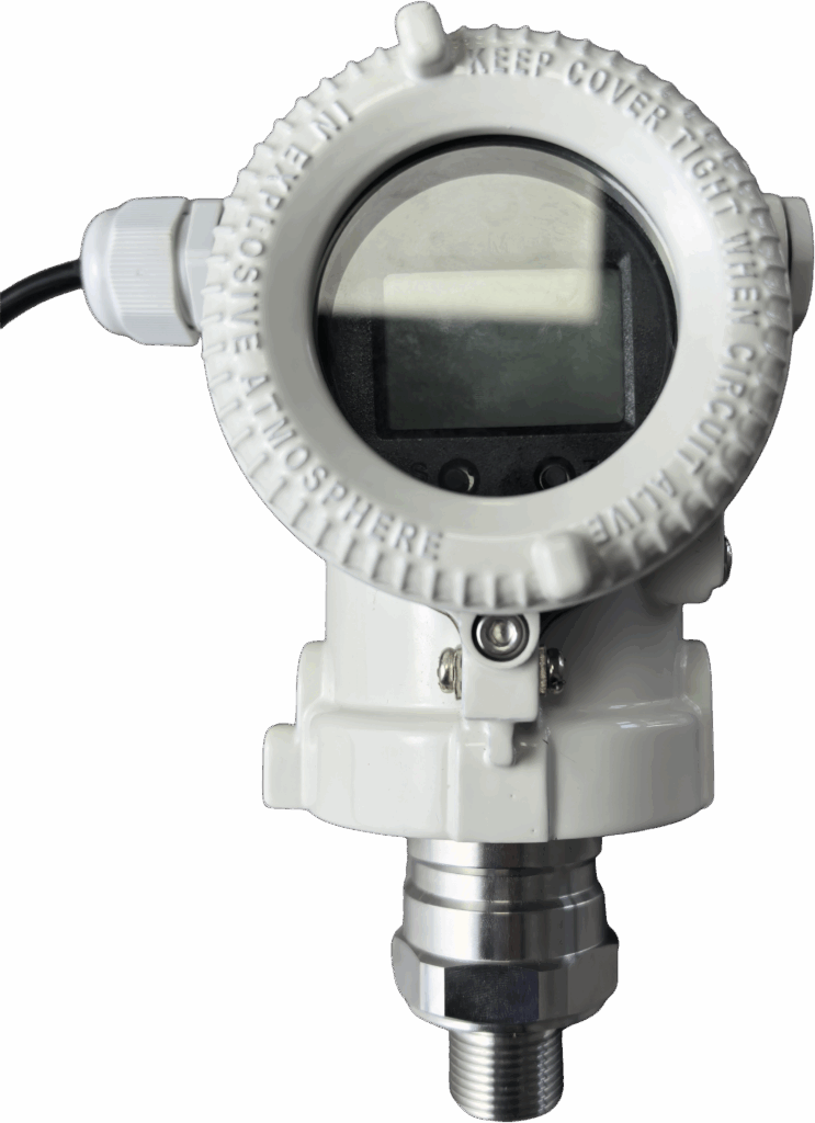
The main reasons why intelligent pressure transmitters cannot accurately measure pressure can be summarized into four categories: problems with the sensor itself, installation and environmental factors, signal transmission and processing problems, and insufficient maintenance and calibration. Among them, zero drift, range deviation, blockage of the pressure guide tube, and temperature effects are the most common causes of failure.
I. Sensor-Specific Issues
Zero Drift
Symptom: Output signal is not 4mA when no pressure is applied (e.g., displays 3.8mA or 4.2mA)
Causes:
Aging of internal components due to prolonged sensor use
Temperature changes causing material expansion and contraction
Unstable power supply voltage
Impact: Even with pressure changes, the measured value will have a fixed deviation, leading to inaccurate system control.
Range Deviation
Symptom: Output signal does not reach 20mA when the pressure reaches the upper limit, or does not reach 4mA at the lower limit
Causes:
Sensor aging or damage (e.g., ruptured diaphragm)
Experienced impact or vibration during installation
Severe overload alters sensor characteristics
Impact: Inaccurate measurement range, potentially causing safety risks or production losses.
Sensor Aging and Wear
Symptoms: Unstable output signal, decreased repeatability
Causes:
Fatigue of sensitive elements due to prolonged use
Corrosive media causing diaphragm performance degradation
Natural aging of electronic components
Impact: Gradually decreases measurement accuracy, especially significant in high-precision applications.
II. Installation and Environmental Factors
Pressure-conducting pipe problems
Symptoms: Slow or no response to pressure changes
Causes:
Pressure-conducting pipe blocked by impurities or particles in the medium (common in fluid measurements containing impurities)
Improper installation of the pressure-conducting pipe (e.g., the presence of high or low points)
Difference in density between the two pressure-conducting pipes due to temperature differences, resulting in pressure head errors
Typical case: After gas pipeline modification, the pressure tapping pipe was directly welded to the pipeline, causing rapid blockage of the pressure-conducting pipe by carbon black.
Improper installation location
Symptoms: Measured values do not match actual values
Causes:
Improper installation height (static pressure shadow in liquid measurements) (Impact)
The sensor diaphragm is not perpendicular to the pressure direction, resulting in insufficient effective pressure component.
Proximity to vibration sources (such as pumps and compressors) causes signal fluctuations.
Impact: May introduce measurement errors of up to 5% or even higher.
Ambient temperature influence
Manifestation: Measurement value drifts with temperature changes.
Causes:
Temperature changes alter sensor material properties (e.g., changes in elastic modulus).
Temperature gradients cause thermal stress, resulting in minor deformation of the sensor structure.
Electronic component parameters change with temperature.
Typical phenomenon: When installed near a large heating furnace, uneven heat dissipation increases measurement error.
High Humidity Environment Issues
Symptoms: Decreased measurement accuracy, unstable signal
Causes:
Moisture enters the transmitter, causing short circuits or corrosion of electronic components.
Humidity affects the dielectric constant of capacitive sensors.
Water droplets condense on the sensor diaphragm surface, altering the diaphragm’s elasticity and mass.
Impact: Prolonged exposure to high humidity significantly shortens the transmitter’s lifespan.
III. Signal Transmission and Processing Issues
Electrical Connection Issues
Symptoms: Signal fluctuations, interruptions, or no output at all
Causes:
Loose wiring or poor contact.
Reversed power supply or insufficient supply voltage (below 12VDC).
Poor cable shielding, leading to electromagnetic interference.
Typical Phenomenon: Output current or voltage values fluctuate continuously even without pressure changes.
Electromagnetic Interference
Symptoms: Abnormal output signal waves.
Causes:
Proximity to large motors, frequency converters, and other strong electromagnetic equipment.
Signal lines and power lines are not routed separately.
Poor grounding or multiple grounding points.
Impact: In strong electromagnetic field industrial environments, this can significantly increase measurement errors.
Signal Processing Issues
Symptoms: Measured value does not correspond to actual pressure
Causes:
Incorrect parameter settings (e.g., improper range or zero point settings)
Communication protocol error or software program problem
Microprocessor malfunction within the intelligent transmitter
Typical phenomenon: Actual pressure value is 5MPa, but the transmitter output displays 3MPa
IV. Insufficient Maintenance and Calibration
Calibration cycle too long
Symptoms: Measurement accuracy gradually decreases
Causes:
Failure to calibrate regularly as specified (generally recommended 6-12 months in industrial applications)
Insufficient calibration cycle in high-precision or harsh environment applications (should be shortened to 3-6 months)
Improper calibration method (e.g., not using a standard pressure source)
Incorrect calibration method
Symptoms: Systematic errors still exist after calibration
Causes:
Adjusting only the output circuit while ignoring the input section
Failure to simultaneously debug input and output
Intelligent transmitter not performed “range setting,” “range re-setting,” and “fine-tuning” as required by the manufacturer
Improper maintenance
Symptoms: Frequent malfunctions, shortened lifespan
Causes:
Failure to regularly check sealing (especially in high humidity environments)
Failure to promptly clean blockages in the pressure-conducting pipe
Failure to check power supply stability and wiring tightness
V. Recommended Solutions
Regular Calibration: Determine the calibration cycle based on the working environment and accuracy requirements. For high-precision applications, calibration every 3-6 months is recommended.
Correct Installation: Ensure the pressure-conducting pipe is short and free of high/low points, the sensor diaphragm is perpendicular to the pressure direction, and it is kept away from vibration sources.
Environmental Protection: Strengthen sealing when used in high humidity environments; add a buffer tube for heat dissipation in high-temperature environments.
Standardized Calibration: Use a standard pressure source and simultaneously test both input and output. For intelligent transmitters, perform a complete calibration process according to the manufacturer’s requirements.
Timely Maintenance: Regularly check for blockages in the pressure-conducting pipe, secure wiring, and stable power supply.
Important Note: When the pressure transmitter is found to be “inaccurate,” first check the power supply, wiring, and pressure-conducting pipe before considering problems with the sensor itself. For intelligent pressure transmitters, their self-diagnostic function can quickly locate the problem. If necessary, contact a professional technician for calibration or repair.
Add me as a friend to learn more.





