

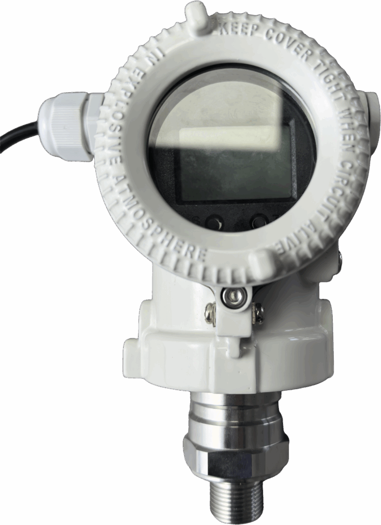
The metrological verification of pressure transmitters is a key link in ensuring the accuracy of industrial process control. Through standardized verification procedures and methods, the accuracy and reliability of pressure measurement can be effectively ensured, providing strong support for production safety and quality control.
I. Purpose and Significance of Verification
Pressure transmitter verification refers to the comprehensive inspection, testing, and adjustment of the pressure transmitter to ensure its performance meets specified requirements.
The main purposes of calibration are:
Verifying accuracy: Ensuring that the pressure transmitter’s measurement results match the actual pressure value, guaranteeing the stability and safety of the production process.
Checking technical specifications: Evaluating whether the pressure transmitter’s key performance indicators, such as measurement range, accuracy, and stability, meet the usage requirements.
Identifying potential problems: Timely identifying and resolving common problems such as zero drift and range error, ensuring long-term stable operation of the equipment.
II. Calibration Items and Requirements
The calibration items for pressure transmitters mainly include:
Visual inspection: Inspecting the pressure transmitter for any damage or deformation, and confirming that the nameplate, specifications, and other information are clear and accurate.
Sealing check: Smoothly pressurizing to the upper limit of the measurement value, then sealing for 15 minutes after shutting off the pressure source, observing for any leakage.
Insulation resistance test: Measuring the insulation resistance between the power supply terminals and the output terminals using an insulation resistance meter to ensure compliance with safety requirements.
Indication error test: Evaluating the measurement error of the pressure transmitter at different pressure points, ensuring it does not exceed the allowable error.
Hysteresis error test: Checking the output difference during the pressurization and depressurization processes at the same pressure point, evaluating the transmitter’s repeatability.
III. Verification Steps and Methods
1. Preparation Before Verification
Thermal Balancing Treatment: Place the pressure transmitter under test and the verification equipment under verification conditions for at least 2 hours to allow them to fully adapt to the environmental conditions.
Equipment Connection: Connect the signal lines and pressure lines according to the specified requirements, ensuring that the pressure transmitter’s pressure tap and the standard’s pressure tap are on the same horizontal plane.
Standard Selection: Select a suitable standard pressure source, such as a digital pressure calibrator or piston gauge, ensuring that its accuracy meets the requirements.
2. Sealing Check
Smoothly increase the pressure until the pressure in the transmitter’s measuring chamber reaches the upper limit of the measurement value. Turn off the pressure source and seal for 15 minutes. Observe the pressure value change in the last 5 minutes.
For AC-powered transmitters, the pressure drop should not exceed 2% of the upper limit of the measurement value.
3. Indication Error Verification
Verification Point Selection: At least 5 points should be selected, evenly distributed across the measurement range, including both the upper and lower limits (at least 9 points for transmitters better than 0.1 class).
Verification Method: Starting from the lower limit, steadily increase the pressure to each verification point and record the output value; then decrease the pressure in the opposite direction to the lower limit and record the output value.
Error Calculation: Indication Error = Actual Output Value – Theoretical Output Value
4. Return Stroke Error Verification
Calculation Method: Return Stroke Error = |Upper Stroke Output Value – Lower Stroke Output Value|
Requirement: The return stroke error should not exceed the allowable error value.
5. Zero Point and Range Adjustment
Zero Point Adjustment: Under no-pressure conditions, adjust the pressure transmitter output to the theoretical zero point value (usually 4mA).
Range Adjustment: Under full-scale pressure, adjust the pressure transmitter output to the theoretical full-scale value (usually 20mA).
Adjustment Methods: Can be performed through mechanical adjustment, HART protocol adjustment, or Brownian protocol adjustment, etc.
IV. Verification Cycle and Result Processing
Verification Cycle
Routine Environment: Generally no more than 1 year.
High Precision or Critical Processes: It is recommended to verify every 3-6 months.
Harsh Environments or Frequent Use: The cycle needs to be shortened, or even verified monthly. 1220 Verification Result Processing
Pass/Fail Judgment: All verification items meet the requirements of the regulations, and a verification certificate is issued.
Failure Handling: Repair or adjust the unqualified items and re-verify. If still unqualified, replacement is required.
Record Requirements: Record detailed verification data, environmental conditions, standard instrument information, etc., for easy traceability and analysis.
V. Precautions and Techniques
Height Difference Correction: When the pressure transmitter’s tap and the standard’s tap are not on the same horizontal plane, height difference correction is required.
Handling Abnormal Situations: If the midpoint error still exceeds the tolerance after adjusting the zero point and range, the calibration curve can be shifted or its slope changed by adjusting the “Z” or “S” knob.
Key Points for On-Site Verification: Before on-site verification, the actual range of the transmitter must be confirmed to avoid errors exceeding tolerance due to range modification.
Safety Requirements: Pressurization operations must strictly adhere to safety regulations and protective measures must be taken, especially in high-pressure and gaseous media applications.
Add me as a friend to learn more.





