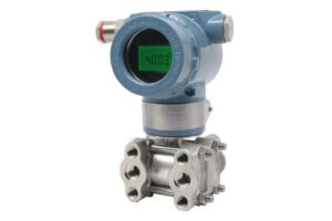
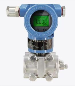
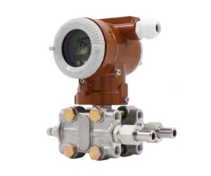
Most on-site maintenance personnel misjudge these abnormal phenomena as instrument failures, leading to unnecessary replacement and repeated calibration without resolving root problems. This article systematically analyzes the intrinsic failure mechanism of vortex meters under pulsating flow, summarizes the core inducing factors including frequency coupling, flow field distortion and signal aliasing, and proposes practical optimization solutions covering installation optimization, parameter debugging and auxiliary rectification. It provides reliable technical guidance for stable and accurate measurement of vortex flow meters under unsteady pulsating working conditions.
1. Introduction
Different from constant and stable fluid conditions in conventional pipelines, pulsating flow features periodic flow velocity fluctuation, instantaneous pressure surge and unsteady fluid impact, which are common in petrochemical transportation, industrial boiler gas supply, reciprocating pump delivery and intermittent process batching. Working based on the Karman vortex street principle, vortex flow meters calculate flow rate by capturing regular vortex shedding frequencies. This working mechanism relies heavily on stable and ordered flow fields. Once encountering periodic pulsating interference, the regular vortex arrangement is destroyed, resulting in mismatched signal frequency and actual flow velocity. In engineering practice, pulsating flow interference is the primary cause of vortex meter inaccurate measurement and false faults, severely restricting process control precision and industrial metering credibility.
2. Core Causes of Vortex Meter Malfunction Under Pulsating Flow
The foremost cause is frequency coupling resonance. Pulsating flow generated by reciprocating pumps and cyclic valves has a fixed fluctuation frequency. When the fluid pulsation frequency overlaps or approaches the natural vortex shedding frequency of the flow meter, frequency superposition occurs. The sensor cannot distinguish valid vortex signals from pulsating interference signals, resulting in signal aliasing, sharp data jitter and extreme measurement deviation. In severe cases, the meter displays disordered flow values and completely loses measurement capability, presenting a typical “失灵” state.
Secondly, pulsating flow triggers severe flow field distortion and turbulence mutation. Steady flow produces regular and continuous vortex streets behind the bluff body, while periodic pulsating impact causes fluid surge, backflow and swirling flow. The disordered fluid destroys the stable vortex generation cycle, leading to uneven vortex spacing and unstable signal amplitude. Different from random noise interference, pulsating interference presents periodic regularity, which cannot be eliminated by conventional signal filtering, resulting in persistent measurement failure.
Thirdly, unreasonable instrument parameter settings amplify malfunction symptoms. Most factory default parameters of vortex meters are calibrated for steady flow. Under pulsating conditions, fixed filtering intensity and response speed cannot adapt to rapid flow fluctuation. Excessively sensitive parameters capture massive interference signals, while excessive filtering causes signal lag and data distortion, further deteriorating measurement stability and causing long-term inaccurate flow monitoring.
3. Targeted Optimization Solutions and On-Site Rectification Measures
To solve vortex meter failure under pulsating flow fundamentally, systematic optimization from installation, pipeline and parameter debugging is required. First, optimize the installation position to avoid pulsation sources. Keep the flow meter away from reciprocating pumps, regulating valves and pressure fluctuation terminals, and reserve sufficient upstream and downstream straight pipe sections to restore flow field stability. Installing flow straighteners and buffer dampers is an effective way to absorb periodic pulsation impact and suppress fluid frequency oscillation.
Second, carry out targeted parameter debugging. Adjust the meter’s signal filtering intensity, frequency response threshold and damping coefficient according to actual pulsation cycles. Appropriately increase adaptive filtering to eliminate periodic interference without affecting effective signal capture, realizing dynamic matching between algorithm parameters and unsteady flow conditions.
Third, adopt pipeline rectification schemes for severe pulsating scenarios. Install buffer tanks, pulsation dampers and pressure stabilizing valves at the front end of the measuring pipeline to weaken fluid periodic fluctuation, convert unsteady pulsating flow into relatively stable flow, and create qualified measuring conditions for vortex flow meters. For working conditions with extreme frequent pulsation, replacing anti-pulsation customized vortex meters or matching differential measurement schemes can completely eliminate malfunction risks.
4. Conclusion
The malfunction of vortex flow meters under pulsating flow conditions is not caused by instrument quality defects, but by the mismatch between the Karman vortex measurement principle and unsteady periodic flow fields. Frequency coupling resonance, flow field distortion and unreasonable parameter settings are the three core inducements of signal disorder and measurement failure. Through reasonable installation layout, pipeline pulsation suppression and adaptive parameter optimization, the anti-interference ability and measurement stability of vortex meters can be effectively improved. Standardized rectification methods can thoroughly solve pulsating flow failure problems, maximize the application advantages of vortex meters, and ensure long-term stable and accurate flow measurement in complex unsteady industrial working conditions.
Scan the QR code to receive more detailed information.