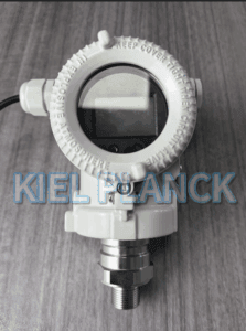
Annual zero and span on-site verification is a mandatory routine maintenance item for industrial instrumentation management. This article systematically introduces the standardized on-site operation steps for annual transmitter verification, including pre-check preparation, static zero calibration, full-scale span verification, error judgment and post-adjustment confirmation. It also summarizes common on-site errors and standardized handling methods. The purpose is to provide field maintenance personnel with a compliant, safe and efficient annual calibration workflow to ensure the long-term measurement accuracy and operational stability of process transmitters.
1. Introduction
In petrochemical, thermal power, new energy and water treatment industries, transmitters work continuously throughout the year under complex working conditions. Even high-precision smart transmitters will produce cumulative drift after long-term operation. Zero drift mainly comes from sensor stress release and ambient temperature changes, while span deviation is caused by aging of internal circuit parameters and long-term pressure fatigue. Most invisible measurement errors will not trigger system alarms but gradually affect process stability, energy consumption statistics and safety interlock accuracy. Therefore, all process transmitters must undergo a complete zero and span verification at least once a year. Different from laboratory calibration, on-site verification needs to consider process safety, equipment interlock suspension and field environmental interference, requiring standardized and rigorous operating specifications.
2. Standard On-Site Verification Process for Annual Zero and Span Check
The first step is pre-operation preparation and safety isolation. Before calibration, maintenance personnel need to confirm the operating state of the pipeline and equipment, suspend relevant automatic interlock and control loops to prevent misoperation caused by signal fluctuation. Isolate the transmitter through the three-valve group, close the positive and negative pressure valves, and open the balance valve to ensure the sensor is in a completely pressure-free state. Meanwhile, prepare standard calibration instruments, multimeter, HART handheld terminal and recording forms to ensure the accuracy of reference equipment.
The second step is on-site zero point verification and adjustment. After pressure relief, observe the transmitter’s real-time output signal. Under ideal zero-pressure conditions, the standard output should be 4 mA. If the displayed value has a slight deviation, perform zero reset through the local button or handheld device. It is critical to distinguish true zero drift from residual pressure interference. If residual medium or static pressure exists in the impulse tube, thorough drainage and pressure relief are required before zero adjustment to avoid false calibration.
The third step is full-scale span verification and correction. After completing zero calibration, apply standard pressure signals of 50% and 100% range to the transmitter in stages. Compare the actual output current with the theoretical standard value, calculate the linear error and full-scale error. For smart transmitters with large span deviation, perform span parameter correction to ensure the linearity of the full range. Field verification focuses on full-scale linearity inspection, because mid-range and high-range deviations are the main causes of inaccurate process adjustment.
The fourth step is error confirmation, data recording and system recovery. After calibration, recheck the zero point and full range again to confirm no repeated drift. Fill in the annual calibration record form, mark the calibration date and error data, and form traceable maintenance files. Finally, close the balance valve, restore the positive and negative pressure pipelines, put the transmitter back into service, and lift the interlock protection suspension to resume normal process automatic control.
3. Common On-Site Mistakes and Standard Solutions
Many field maintenance problems occur during annual verification. Blind zero adjustment without pressure relief is the most common mistake, leading to larger measurement errors. In addition, many personnel only calibrate the zero point and ignore span verification, resulting in good zero-point accuracy but poor full-range linearity. Moreover, failing to suspend interlocks in advance may cause production fluctuation and safety risks. For transmitters with severe drift, simple zero-span adjustment is not enough; further inspection of sensor aging, impulse tube blockage and seal damage is required to eliminate hidden faults fundamentally.
4. Conclusion
Annual zero and span on-site verification is an indispensable basic maintenance work to maintain long-term accuracy of industrial transmitters. Standardized processes including safety isolation, zero reset, full-scale span calibration, error analysis and data filing can effectively eliminate annual cumulative drift of instruments. Field maintenance teams should strictly implement annual calibration specifications, avoid incomplete calibration and irregular operation, and combine regular verification with daily inspection. Scientific annual calibration management can ensure stable and reliable output of transmitter signals, optimize process control accuracy, and support safe, stable and efficient operation of industrial production systems.
Scan the QR code to receive more detailed information.