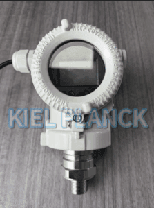
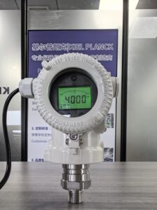
Many field teams only rely on simple heat tracing and ignore subtle but critical details, resulting in recurring winter instrument faults. This article summarizes five practical freeze-protection details for pressure transmitters, covering impulse tube layout, drain and vent design, heat tracing configuration, filling fluid selection for remote diaphragm seals, and daily winter inspection protocols. It analyzes common freeze-induced failure mechanisms and provides actionable on-site operation guidelines. This paper helps project and maintenance teams in northern regions avoid winter instrument downtime and maintain stable pressure measurement throughout cold seasons.
1. Introduction
From October onward, northern China enters a rapid cooling period. Outdoor instruments for chemical, heating, water treatment and new energy projects are exposed to sub-zero temperatures overnight. Pressure transmitters are highly vulnerable to freezing damage because residual liquid trapped in impulse lines or sensor chambers expands when ice forms. The volume expansion can crush the sensing diaphragm, block pressure signal transfer and even crack pipe fittings. Many maintenance teams apply heat tracing as the sole anti-freezing measure, yet freezing accidents still occur frequently. The root cause lies in overlooking small design and maintenance details. Effective winter protection requires systematic management from piping design, auxiliary configuration to regular inspection. Mastering these five core details can greatly reduce the failure rate of pressure transmitters during cold weather.
2. Five Key Freeze Protection Details for Pressure Transmitters
2.1 Optimize impulse pipe routing and slope to eliminate liquid trapping
The first detail is impulse tube layout. Impulse piping should be designed with a continuous slope toward the process pipeline to avoid low pockets where liquid stagnates. Low-lying dead sections trap condensate or process water, which is the primary freezing point. Avoid unnecessary horizontal long runs and U-shaped bends. If dead legs cannot be eliminated, add drain valves at the lowest points to regularly drain accumulated liquid. Even with heat tracing, trapped liquid may freeze if the tracing power is insufficient or interrupted. Removing liquid trapping points is the most fundamental anti-freezing measure.
2.2 Correctly configure heat tracing and insulation layers
Heat tracing is widely used, but improper installation causes failures. Users must select suitable electric or steam tracing according to the minimum ambient temperature. The tracing cable should be tightly attached to impulse tubes and transmitter manifolds instead of loosely wrapped. Insulation jackets must fully cover both pipes and instrument body. Gaps in insulation, especially at joints and valve manifolds, become cold bridges and cause local freezing. Overheating should also be prevented; excessive temperature may damage the transmitter electronics or degrade filling oil in capillary seals. Temperature controllers are recommended to maintain a stable temperature above freezing point.
2.3 Properly manage remote diaphragm seal filling fluid
For transmitters fitted with capillary remote seals, the filling fluid is critical for cold resistance. Standard filling oil will thicken or solidify under low temperature, causing signal drift and slow response. For northern winter conditions, low-temperature anti-freeze filling fluid must be selected according to the lowest design ambient temperature. Check for leakage of capillary lines before winter. Tiny leaks reduce filling liquid volume and allow air ingress, leading to measurement deviation and local freezing inside the capillary. Any damaged capillaries should be replaced before cold weather arrives.
2.4 Install drain/vent valves and implement pre-winter draining procedures
Before October cold snaps arrive, carry out pre-winter draining for impulse lines. Install drain valves at the lowest points and vent valves at high points to remove residual water and condensate. For systems that can be isolated, fully drain static liquid during shutdown periods. Many freeze failures happen during standby conditions, when static liquid remains inside the impulse pipe with no flow to generate heat. Establish a scheduled draining checklist for static instrument loops, especially for infrequently monitored points.
2.5 Build targeted winter inspection and alarm mechanisms
Routine winter inspection is the fifth key detail. Maintenance teams should add pressure transmitters to cold-season patrol checklists. Inspect heat tracing power supply, insulation integrity, and drain valve status. Monitor transmitter zero drift as an early warning sign of partial freezing. Set up temperature alarms for heat tracing circuits to alert operators when tracing power fails. Many freeze accidents occur overnight or during holidays, when loss of heat tracing is undetected for hours. Timely alarm and patrol can prevent small issues from developing into permanent sensor damage.
3. Common Misconceptions to Avoid
A common mistake is believing heat tracing alone can solve all freezing risks. Heat tracing cannot compensate for poor piping design with trapped liquid. Another error is using ordinary filling oil for capillary seals in extremely cold environments. Even with heat insulation, low ambient temperature may still cause oil viscosity surge and measurement distortion. In addition, maintenance teams often skip pre-winter draining, assuming process flow will prevent liquid accumulation. Static condensate is the main culprit for instrument freezing on northern sites.
4. Conclusion
Starting from October, northern industrial projects must prioritize freeze protection for pressure transmitters. Five essential details include eliminating liquid trapping in impulse piping, standardized heat tracing and insulation, selecting low-temperature filling fluid for diaphragm seals, implementing pre-winter draining, and establishing winter inspection and alarm systems. Freeze damage is mostly caused by accumulated static liquid and weak points in insulation or tracing, rather than low temperature itself. By implementing these five measures, engineering and maintenance teams can effectively prevent diaphragm rupture, signal blockage and equipment downtime. Proper winter protection ensures continuous and reliable pressure measurement for northern process systems throughout the cold season.
Scan the QR code to receive more detailed information.