

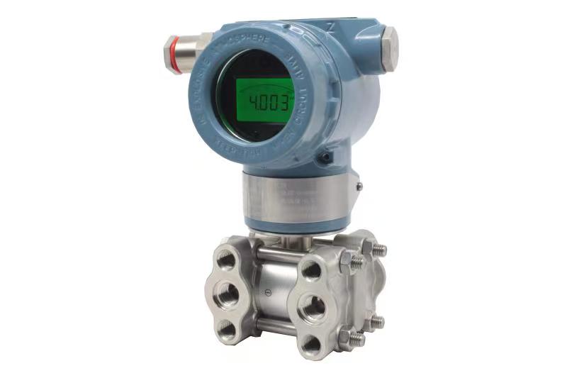
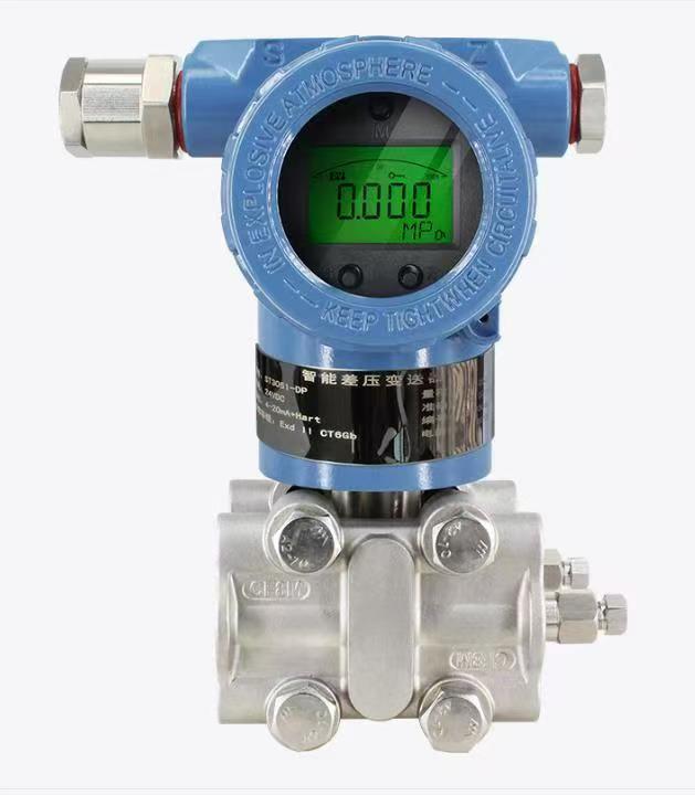
Differential pressure transmitters are core measuring instruments widely applied in industrial process control for flow, liquid level, and pressure monitoring. The installation quality of positive and negative pressure taps directly determines the accuracy and stability of measurement data, while liquid accumulation in pressure taps and impulse lines is one of the most common causes of zero drift, signal deviation and frequent measurement errors. This article systematically summarizes standardized installation specifications for pressure taps under gas, liquid and steam working conditions, analyzes the error mechanisms induced by liquid accumulation, and proposes targeted installation and maintenance optimization measures. Following professional installation standards can effectively eliminate residual liquid in pressure guiding systems, balance the pressure transmission of positive and negative pressure sides, reduce systematic measurement errors, and improve the long-term operational reliability of differential pressure transmitters in industrial production.
1. Introduction
In petrochemical, power, pharmaceutical and other process industries, differential pressure transmitters rely on positive and negative pressure taps to collect process pressure signals and convert pressure differences into standard electrical signals for system control. In actual engineering applications, unscientific tap position selection, unreasonable pipeline layout and non-standard construction often lead to liquid condensation and accumulation in pressure taps and impulse lines. Accumulated liquid will generate additional hydrostatic pressure, break the pressure balance between the high-pressure (positive) and low-pressure (negative) sides, and cause persistent measurement errors. Even tiny liquid residues can lead to inaccurate data transmission, affect process parameter adjustment, and trigger production instability risks. Therefore, strict compliance with standardized installation specifications for positive and negative pressure taps is essential to avoid liquid accumulation and ensure precise measurement.
2. Mechanism of Measurement Errors Caused by Liquid Accumulation
The working principle of differential pressure transmitters is based on the pressure difference between positive and negative pressure ports. The pressure guiding system must maintain a uniform and stable medium state to ensure accurate pressure transmission. When liquid accumulates in pressure taps or impulse lines, the residual liquid forms extra hydrostatic pressure that cannot be offset synchronously on both sides. If liquid accumulates unevenly on the positive and negative pressure sides, the actual pressure difference received by the transmitter will deviate from the real process pressure difference, resulting in zero offset and linear errors. In addition, long-term accumulated liquid may cause pipeline corrosion, blockage and medium stratification, further aggravating signal fluctuation and even leading to instrument failure, which seriously interferes with normal process monitoring and control.
3. Standard Installation Specifications for Pressure Taps Under Different Working Conditions
The core principle of pressure tap installation is to select reasonable positions and layouts according to process medium characteristics to fundamentally prevent liquid accumulation and ensure consistent pressure transmission on positive and negative sides.
For gas medium measurement, pressure taps should be arranged at the top or upper side of the process pipeline. This layout enables condensed liquid in the pipeline to flow back to the process pipe by gravity, avoiding deposition in pressure taps and impulse lines. The transmitter should be installed above the measuring point to ensure all condensate can drain back smoothly, eliminating residual liquid interference.
For liquid medium measurement, pressure taps must be set on the horizontal side or lower side of the pipeline, and installation at the pipeline top is strictly prohibited to prevent gas from entering the pressure guiding system. The transmitter should be mounted below the measuring point to keep impulse lines fully filled with process liquid, avoid gas accumulation, and ensure stable and consistent pressure transmission on both positive and negative sides.
For steam medium measurement, pressure taps are installed on the side of the pipeline. It is mandatory to install height-consistent condensate pots on both positive and negative pressure sides. The equal hydrostatic head of condensed water in the two pots can balance the pressure difference, avoid liquid level deviation caused by uneven condensation, and prevent liquid accumulation and measurement deviation. Meanwhile, impulse lines shall be equipped with drain valves to regularly discharge residual condensed liquid.
4. Auxiliary Installation and Maintenance Optimization Measures
On the basis of standardized tap position selection, standardized pipeline laying and regular maintenance are also key to avoiding liquid accumulation. Impulse lines shall be laid with a reasonable slope to ensure automatic drainage of condensed liquid, without concave bending or horizontal dead zones that easily store liquid. A three-valve manifold is recommended for matching installation to facilitate zero calibration, pressure balancing and pipeline flushing. For easy-crystallization and viscous media, isolation tanks or flushing rings should be installed to prevent medium deposition and liquid retention. In addition, regular inspection and drainage of pressure taps and impulse lines can eliminate hidden dangers of liquid accumulation in time.
5. Conclusion
Liquid accumulation in positive and negative pressure taps is a major factor causing measurement errors of differential pressure transmitters. Scientific and standardized tap installation is the primary means to solve this problem. According to different medium characteristics, selecting targeted tap positions, matching reasonable pipeline layout and auxiliary equipment, and cooperating with daily maintenance can completely avoid liquid accumulation in pressure guiding systems, ensure balanced and accurate pressure signal transmission, and effectively reduce systematic measurement errors. Standardized installation specifications not only improve the measurement accuracy and operational stability of differential pressure transmitters, but also provide reliable data support for safe, stable and efficient operation of industrial process systems.
Scan the QR code to receive more detailed information.





