

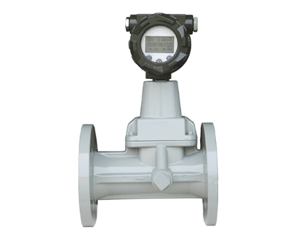
The daily maintenance of vortex flowmeters should focus on key aspects such as regular cleaning, pressure coefficient adjustment, component inspection, electrical maintenance, and troubleshooting to ensure measurement accuracy and long-term stable operation of the equipment.
I. Regular Cleaning and Inspection
1. Internal Liquid Cleaning System
Establish a periodic cleaning plan: Determine the optimal cleaning cycle based on the operating environment and media characteristics, typically performing a comprehensive cleaning every 3-6 months.
Cleaning Important Parts: Emphasize cleaning irrelevant liquids, vortex generators, and dirt from the sensor surface inside the flowmeter to prevent sediment and crystals from affecting measurement accuracy.
Cleaning Method: Gently wipe with a soft cloth or sponge. Avoid using water, chemical cleaners, or hard objects to avoid interfering with normal operation or damaging sensitive components.
2. Mechanical Component Inspection
Impeller Inspection: Regularly check the impeller’s rotation and smoothness. Replace immediately if wear or aging is found, ensuring the turbine’s dynamic balance.
Inlet and Outlet Valve Maintenance: Check valve sealing to ensure no leaks. Valves should be installed on the back of the flowmeter to avoid liquid impact.
Flange Connection Inspection: Check flange connections monthly for leaks. Tighten loose bolts promptly to ensure good sealing performance.
II. Parameter Adjustment and Calibration
1. Dynamic Adjustment of Pressure Coefficient
IV. Common Fault Troubleshooting and Handling
1. No Instantaneous Flow Rate Display
Possible Causes: Flow meter lower limit cutoff frequency set too high; insufficient preamplifier voltage; vortex generator blocked by debris; measured flow rate below the range.
Solutions: Change the lower limit cutoff frequency to a value greater than 1; check battery voltage (should be ≥2.9V); clean the vortex generator and probe; confirm the flow rate is within the range.
2. Abnormal Temperature Display
Possible Causes: Damaged temperature sensor (displaying “-75℃” or >100℃); temperature and pressure circuit malfunction.
Solutions: Replace the temperature sensor; if the problem persists after replacement, check and replace the temperature and pressure circuit.
3. Abnormal Pressure Display
Possible Causes: Damaged pressure sensor; blocked pressure tap; deteriorated linear calibration curve.
Solutions: Test with a new external pressure sensor; clean the pressure tap; recalibrate or replace the pressure sensor.
4. Unstable flow meter display
Possible causes: Improper amplifier sensitivity setting, pipeline vibration, poor grounding, unstable medium flow rate.
Solutions: Adjust or replace the preamplifier; eliminate the vibration source; check and improve grounding; ensure stable fluid flow rate.
V. Operating Environment and Safety Maintenance
1. Environmental Condition Control
Avoid Adverse Environments: Avoid installing the flowmeter in high-temperature (>60℃), humid, or strong electromagnetic field environments to prevent thermal expansion of sensor materials or corrosion of electrical components.
Outdoor Protection: When installed outdoors, it should be covered to avoid direct sunlight and rain erosion, which can affect its service life.
2. Safe Operating Procedures
Start-up and Shutdown: When starting, open the upstream and downstream valves slowly to avoid sudden airflow damaging the vortex starter; when shutting down, turn off the gas supply first, then disconnect the power supply.
Maintenance Safety: During commissioning and maintenance, always turn off the gas supply to ensure safety; avoid operation in high-temperature or humid environments.
3. Explosion-Proof Requirements
Explosion-Proof System: Do not alter the wiring method of the explosion-proof system yourself to ensure the explosion-proof performance of the instrument, especially when used in flammable and explosive environments.
By strictly implementing the above maintenance methods, the service life of the vortex flowmeter can be effectively extended, the measurement error can be controlled within ±0.5%, the failure rate can be significantly reduced, and reliable flow measurement data can be provided for industrial production. It is recommended to establish complete maintenance records, including key information such as cleaning, calibration, and parameter adjustments, to facilitate subsequent tracking and analysis.
Scan the QR code to receive more detailed information.





