

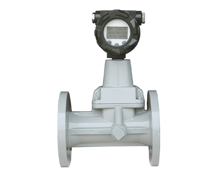
The gas vortex flow meter utilizes the fluid vortex precession effect, integrates automatic temperature and pressure compensation, and is suitable for metering clean and dry gases such as natural gas and compressed air. It is an intelligent velocity flow meter with high accuracy, no mechanical wear, wide range, and easy installation and maintenance.
I. Overview
The Vortex Precession Flow Meter is a velocity-type flow meter specifically designed for cleaning and drying single-phase gases. Based on the fluid vortex precession effect, it integrates flow rate, temperature, and pressure detection, and can automatically compensate for and output a standard volumetric flow rate. It is widely used in trade metering and process control for natural gas, compressed air, biogas, etc.
II. Working Principle
Swirl Initiation: Gas flows through the inlet helical guide vanes (vortex generator) and is forced to rotate, forming a high-speed vortex flow at the center.
Precession: The vortex accelerates after entering the Venturi contraction section, and in the diffusion section, backflow generates gyroscopic precession (the vortex center spirals around the pipe axis).
Detection: A piezoelectric sensor detects the precession frequency (linearly proportional to the flow velocity/volume flow rate), and after signal processing and temperature and pressure compensation, outputs a standard flow signal.
III. Structural Composition
Housing: Carbon steel/stainless steel, pressure-bearing (1.6–6.3 MPa), protecting internal components.
Vortex Generator (Swirl Initiator): Helical blades generate stable vortices.
Venturi Tube Section: Contraction + Diffusion structure enhances the vortex advance effect.
Sensor Components:
· Flow Rate: Piezoelectric sensor (dual detection, vibration resistant).
· Temperature/Pressure: Built-in platinum resistance thermometer and pressure transmitter for real-time compensation.
Converter (Integrator): Microprocessor, signal processing, compensation, display, and output (pulse / 4–20 mA/RS485).
Deswirl Converter: Outlet rectification, eliminating wake vortices and protecting downstream equipment.
IV. Core Features
✅ Advantages
No moving mechanical parts: Wear-resistant, long lifespan (>10 years), low maintenance.
High accuracy: ±0.5%–±1.0% (trade grade), good repeatability.
Wide range ratio: 1:20–1:30, accommodating both small and large flow rates.
Automatic temperature and pressure compensation: Direct output of standard flow rate (Nm³), suitable for trade settlement.
Short straight pipe section: ≥5DN upstream, ≥2DN downstream, space-efficient installation.
Low power consumption: Lithium battery powered, allowing continuous operation for over 5 years.
❌ Limitations
Media Restriction: Only applicable to clean, dry single-phase gases; not suitable for liquids, vapors, or gases containing droplets/dust/strong corrosives.
Low Flow Rate Dead Zone: Accuracy decreases at flow rates < 1 m/s; a cutoff flow rate must be set.
Vibration Sensitivity: Strong mechanical vibrations can easily interfere with the signal; vibration isolation or damping devices are required.
Medium Pressure Loss: Approximately 0.05–0.2 bar; calculations are required for low-pressure conditions.
V. Technical Parameters
Nominal Diameter: DN15–DN300.
Range Ratio: 1:20 / 1:30.
Accuracy Class: ±0.5%, ±1.0%.
Medium Temperature: -20℃~+70℃ (optional -40℃~+120℃).
Operating Pressure: 1.6 / 2.5 / 4.0 / 6.3 MPa.
Output Signal: Pulse, 4–20 mA, RS485 (Modbus).
Power Supply: DC24V or lithium battery (3.6V).
VI. Typical Applications
Oil & Gas: Natural gas transmission and distribution metering, wellhead/storage monitoring.
City Gas: Gate stations, pressure regulating stations, accurate metering for industrial and commercial users.
Industrial Gases: Compressed air, nitrogen, oxygen, hydrogen flow monitoring.
Metallurgy/Chemical Industry: Metering of blast furnace gas, converter gas, and process gases.
Environmental Protection and New Energy: Metering of biogas, coalbed methane, and landfill gas recovery.
VII. Installation Points
Straight Pipe Sections: ≥5DN upstream, ≥2DN downstream; avoid bends, valves, and other flow-damping components.
Media State: Gas must be dry and free of droplets; when installing horizontally, the sensor should face upwards to avoid condensation.
Vibration Isolation: Keep away from pumps, compressors, and other equipment that vibrates strongly; add vibration damping pads or flexible joints if necessary.
Flow Direction: Strictly follow the arrow direction on the casing.
VIII. Comparison with Similar Instruments
vs Orifice Plate Flow Meter: Higher accuracy, wider range, shorter straight pipe section, less maintenance.
vs Vortex Flow Meter: Swirl flow meter offers higher signal-to-noise ratio and better stability at low gas flow rates; vortex flow meters are more suitable for large diameter/steam applications.
vs Turbine Flow Meter: No moving parts, longer lifespan, better resistance to dirt (clean gases).
Scan the QR code to receive more detailed information.





