

Problems encountered during the use of metal rotor flowmeters can be resolved through three steps: accurate diagnosis of the cause, targeted handling, and standardized preventive measures, ensuring long-term stable operation of the flowmeter and maintaining measurement accuracy.
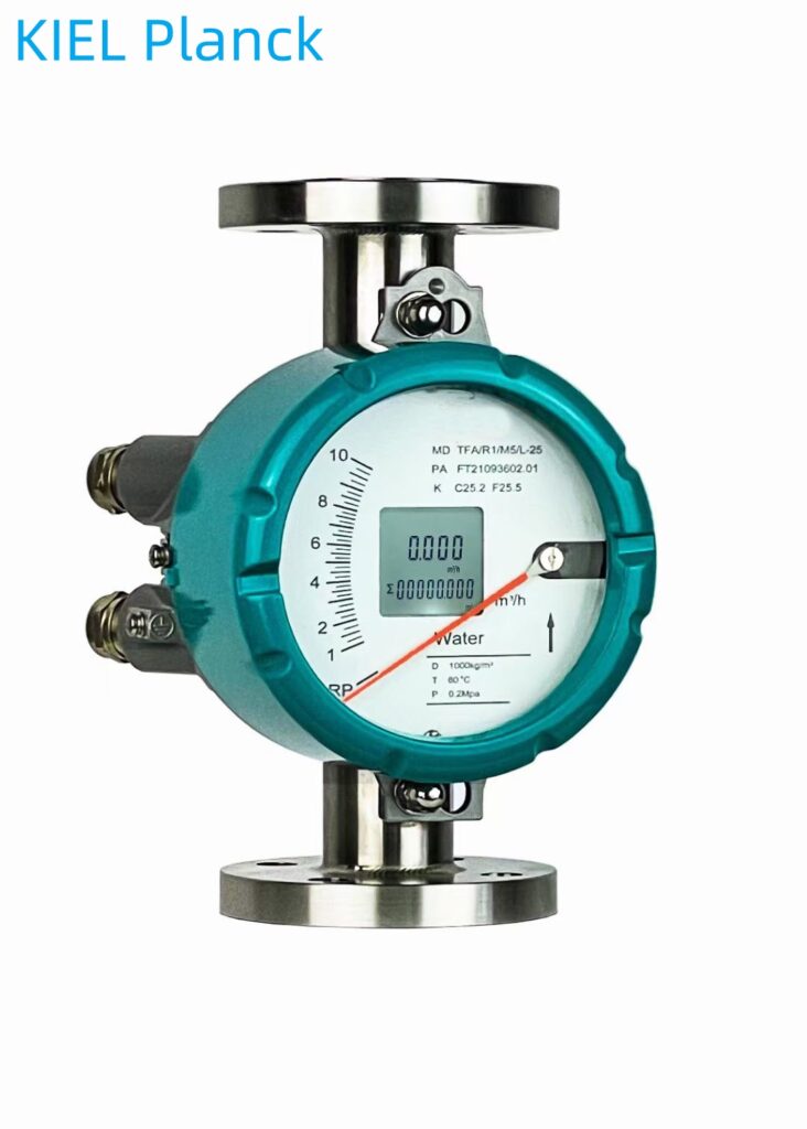
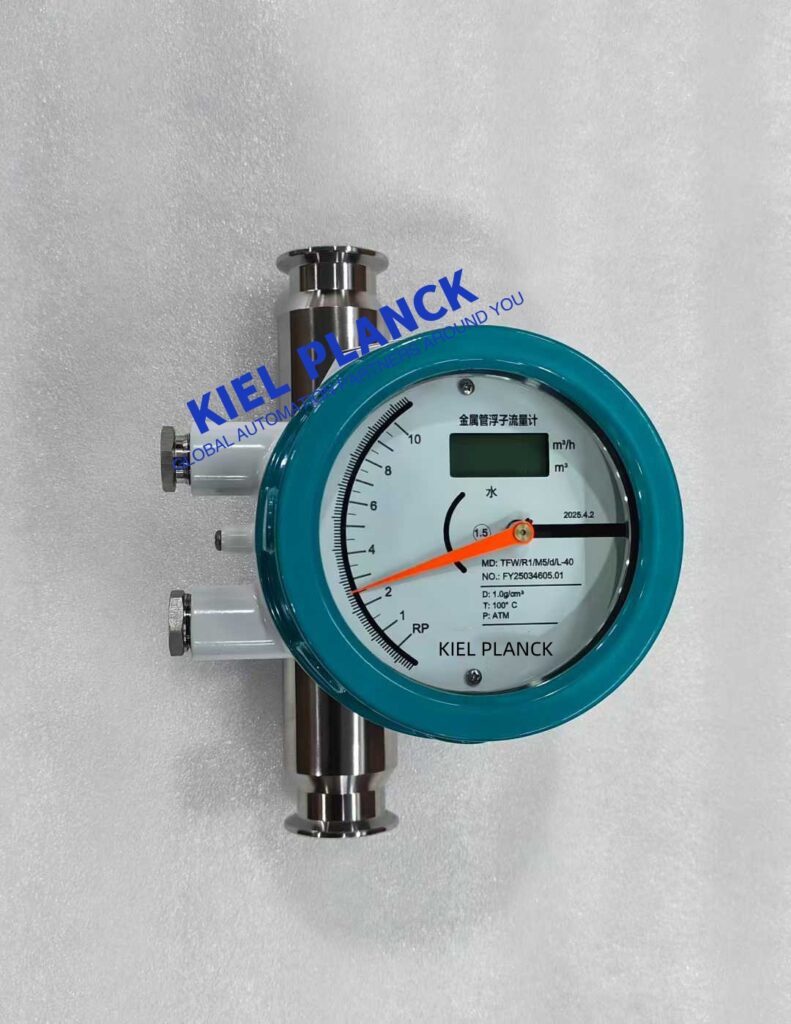
I. Common Problem Diagnosis and Solutions
1. Pointer Malfunction
Pointer does not return to zero
Causes: Excessive medium flow causing overload, impurities blocking the float, instrument impact causing component deformation, loose indicator position, deformed stopper
Solutions:
Open the instrument cover to return the pointer to zero (applicable to excessive flow).
Remove the instrument and clean the float and impurities in the pipeline, ensuring the float moves freely.
Check internal parts for bending or deformation; contact the manufacturer for repair or replacement if necessary.
Adjust the indicator position to “Rp” (non-operating state), check if the LCD display is zero, and tighten the fixing screws.
Remove the float and check the stop. Check for deformation of the device; reshape or replace it.
Pointer jitter or excessive fluctuation
Causes: Slight jitter is caused by medium fluctuation; moderate jitter is caused by unstable medium flow or pressure; severe jitter is caused by medium pulsation or unstable air pressure.
Solutions:
Slight jitter: Overcome by increasing damping.
Moderate jitter: Use a pressure or flow stabilizing device, or increase the air damping of the rotor flowmeter.
Severe jitter: Check if the pressure, temperature, and flow rate provided by the user match the actual conditions to avoid over-range operation of the rotor flowmeter.
Pointer stops at a certain position.
Cause: Float jamming, usually caused by opening the valve too quickly, causing the float to rapidly impact the stop and deform; or misalignment between the rotor guide rod and the stop ring.
Solution:
Remove the instrument and remove the deformed stop rod for reshaping.
Check for concentricity with the guide rod; if misalignment occurs, correct it.
Manually push the rotor to ensure unobstructed movement.
2. Measurement Accuracy Issues
Large Measurement Error
Causes: Improper installation, significant changes in medium density, gas medium affected by temperature and pressure, loosening of components due to long-term use
Solutions:
Ensure vertical installation (tilt angle ≤ 20°) or horizontal installation (tilt angle ≤ 20°), with no ferromagnetic objects within 100mm.
Substitute the changed medium density into the formula to convert it into an error correction coefficient and correct the measurement result.
Use temperature and pressure compensation for gaseous media to obtain the true flow rate.
Verify by manually pushing the pointer; with the pointer at the RP position, check if the output is 4mA and the flow rate display is 0%.
Inaccurate Flow Rate Display/Frequent Value Fluctuations
Causes: Unstable fluid velocity, presence of gas-liquid two-phase flow, excessive gap in the magnetic coupling system, pipeline vibration, loose wiring of the transmitter module.
Solutions:
Investigate upstream fluid disturbance sources and stabilize medium flow rate and operating conditions.
Inspect the magnetic coupling assembly; adjust the gap or replace magnets with deteriorated magnets.
Install pipe vibration damping supports to isolate vibration interference.
Tighten wiring terminals, troubleshoot transmitter circuit faults, and replace damaged electronic components.
3. Signal and Display Issues
No Current Output
Causes: Wiring error, LCD displays but no output, calibration value lost
Solutions:
Check wiring for correctness.
LCD displays but no output, often due to a faulty output transistor; circuit board replacement is required.
Use data recovery operation, or set data in passwords 2000 and 4011, and manually calibrate the pointer from RP to 100%.
No On-Site Display
Causes: Wiring error, power supply problem, improper LCD module installation
Solutions:
Check wiring for correctness.
Check power supply for correctness.
Reinstall the LCD module and check for secure contact.
Check if terminals 12 and 13 are connected to an ammeter or short-circuited.
Incorrect Alarm
Causes: Deviation setting d value too large, logic function error, alarm value setting improper
Solutions:
Check that the deviation setting d value is not too large.
In the FUN function, check if the logic function is correct (HA-A indicates upper limit positive logic, LA-A indicates lower limit positive logic).
Check the alarm value setting in SU.
4. Mechanical and Structural Problems
Float stuck
Causes: Medium contains impurities, high viscosity, improper installation; wear and deformation of the guide mechanism; non-vertical installation
Solutions:
Disassemble the instrument and clean the float, tapered tube, and guide mechanism of impurities and dirt. Install a pipeline filter if necessary.
Check the wear of the guide mechanism and replace damaged parts.
Recalibrate the instrument’s verticality to ensure the vertical deviation meets specifications.
Media leakage at instrument connection
Causes: Aging or damaged seals, flange/threaded connection not tightened properly.
Solutions:
Stop the instrument, drain the medium, and replace the aged gasket.
Retighten the connecting bolts evenly to ensure a tight seal.
If a damaged measuring tube is detected, replace the measuring body immediately.
II. Problem Prevention and Maintenance Recommendations
1. Installation Specifications and Precautions
Vertical Installation: Metal rotor flowmeters must be installed vertically with an inclination not exceeding 2°, ensuring fluid flows from bottom to top through the instrument.
Straight Pipe Section Requirements: A straight pipe section of at least 5 times the pipe diameter should be present at the inlet, and a 250mm straight pipe section should be present at the outlet.
Pipe Cleaning: Before installation, all welding slag inside the pipe must be thoroughly cleaned to prevent foreign objects from entering the flowmeter.
Special Media Handling: When the medium contains solid impurities, a filter should be installed between the valve and the straight pipe section; for gas measurement, ensure the pipeline pressure is not less than 5 times the pressure loss of the flowmeter.
2. Routine Maintenance Points
Regular Cleaning: Clean the float and inside the pipes monthly to prevent sediment or impurities from causing the float to jam.
Sealing Inspection: Check the wear of the seals quarterly to ensure there are no fluid leaks; check the tightness of the connections.
Calibration Cycle: Calibrate the flow meter every six months to verify the consistency between the 4-20mA signal output and the scale indication.
Environmental Control: Avoid installing the flow meter in direct sunlight or in environments with temperatures ≥65℃ to prevent aging of the LCD display module.
3. Special Operating Condition Strategies
High-Temperature Media: When the medium temperature >220℃ or is prone to crystallization, a jacketed flowmeter should be selected. Cooling or insulation measures should be used to maintain the stability of the float’s movement.
Corrosive Media: Select a suitable lining material based on the acidity or alkalinity of the wastewater. For example, PTFE (polytetrafluoroethylene) is suitable for strong acid and alkali environments.
Vibration Environment: Under conditions of strong vibration, additional pipe support is required to reduce vibration transmission and prevent hysteresis errors caused by inertial movement of the float.
III. Troubleshooting Procedure
When a metal rotor flowmeter malfunctions, it is recommended to troubleshoot using the following procedure:
Preliminary Observation: Check the pointer status, LCD display, and external connections.
Environmental Inspection: Confirm whether the installation location meets requirements and check for vibration and electromagnetic interference.
Parameter Verification: Check whether the medium parameters (flow rate, pressure, temperature) are within the instrument’s range.
Mechanical Inspection: Gently tap the flowmeter casing to observe the float’s response and determine if it is jammed.
Electrical Inspection: Check whether the wiring, power supply, and signal output are normal.
Professional Diagnosis: If you cannot resolve the issue yourself, contact a professional technician for diagnosis.
Scan the QR code to receive more detailed information.





