

Electromagnetic Flowmeter Batch Control Function Description
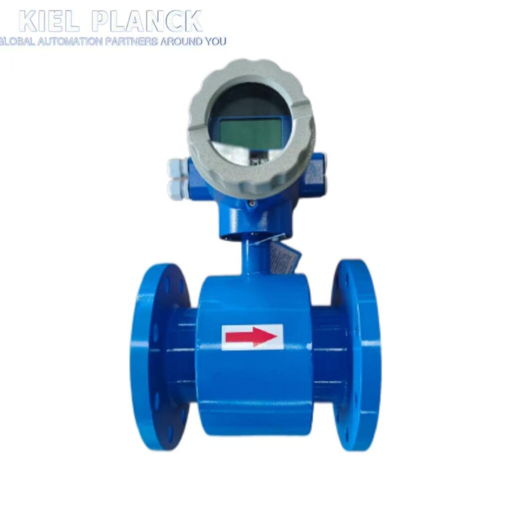
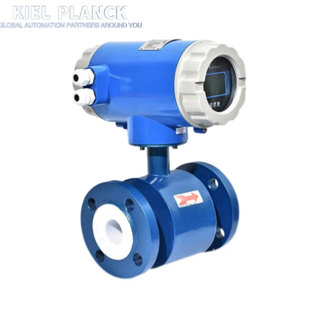
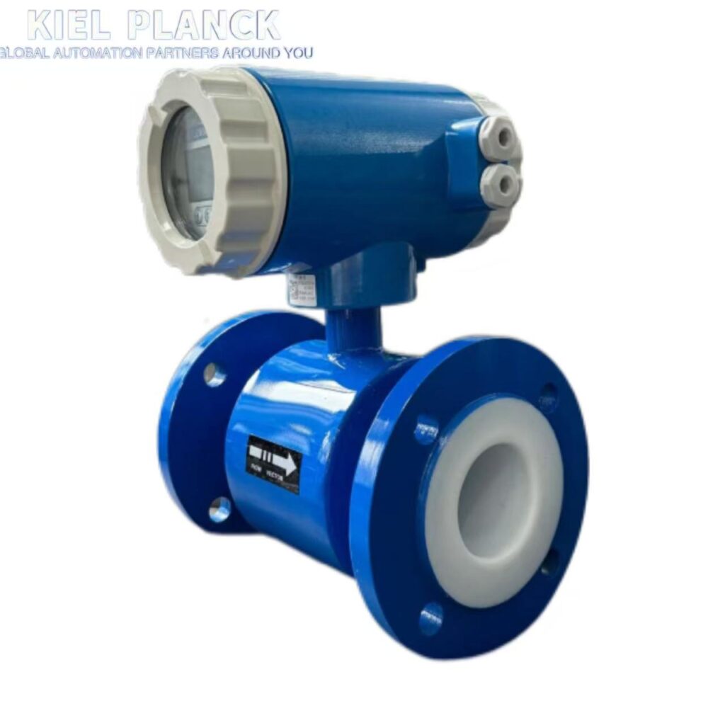
I. Basic Principles of Batch Control Function
Core Mechanism: The electromagnetic flowmeter operates based on Faraday’s law of electromagnetic induction. When a conductive liquid passes through a magnetic field, an induced electromotive force is generated. The flow rate is calculated by measuring this signal. Batch control is achieved through a built-in batch controller. When the accumulated flow rate reaches a preset value, a switch signal is output to control external equipment.
Two Typical Control Modes
Fixed Quantity Metering Control: Meters a fixed amount each time. When the set amount is reached, a switch signal is output to the actuator (e.g., a solenoid valve).
Flow Stabilization Control: Maintains a stable flow rate of the medium in the pipeline, dynamically adjusting the actuator according to flow rate changes.
II. Interface Signals and Parameter Settings
Key Interface Signals
Input Signals: Use AH and COM terminals. When both ends are short-circuited (switch closed), the total control value (ΣS) is cleared to zero. The response time is 300ms. A control signal with a time width greater than 300ms must be provided.
Output Signals: Use the AL terminal as the control signal output. The common terminal is COM. AL outputs a low level when the set value is reached.
Parameter Setting Points
Total Control Value: The settable range is MAX59999. This value represents the last five significant digits of the total control value ΣS, not a single unit value (e.g., 59999m³ or 59999L).
Setting Precautions: The value must be set reasonably according to the actual application requirements to avoid control failure due to improper settings.
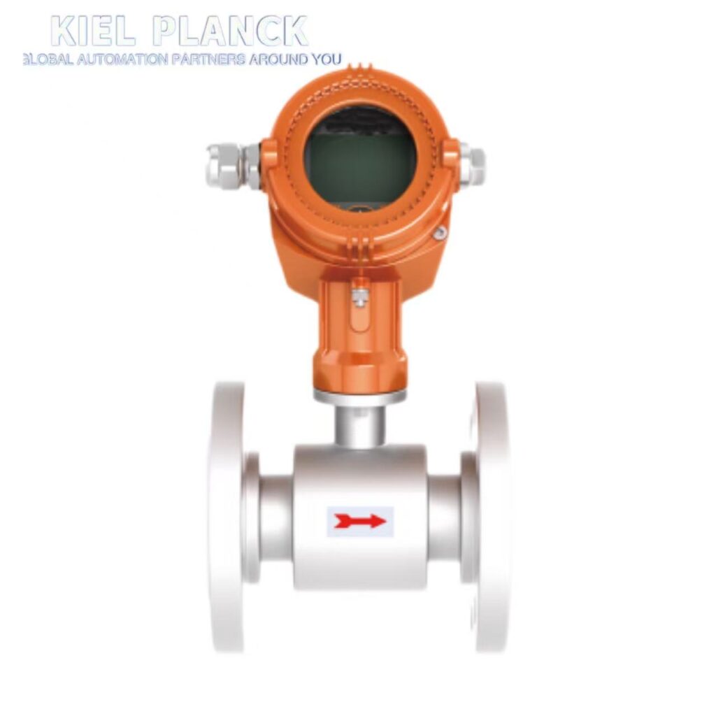
III. Operation Control Flow
Control Cycle Steps
Reset Phase: Use the AH input control terminal to reset the total control quantity (ΣS) to zero (if the switch remains closed, the reset process continues).
Accumulation Phase: Input a high level to the AH input control terminal (switch open), and the total control quantity (ΣS) begins to accumulate.
Trigger Phase: When the accumulated value reaches the set value, the AL outputs a low level (switch closed), completing one control cycle.
Communication Support: The accompanying communication software is L-Mag-P-51, providing dedicated command communication for batch control over single-machine communication, supporting remote monitoring and parameter adjustment.
IV. Typical Application Scenarios
Filling and Feeding Systems: Electromagnetic flow meters, in conjunction with solenoid valves or pneumatic valves, achieve fixed-value batch control, widely used in liquid filling processes in the food and beverage, chemical, and pharmaceutical industries.
Industrial Production Processes
Salt Slurry Discharge: Precisely controls salt slurry flow in the chemical and metallurgical industries.
Wash Water Flow: Achieves flow control under high temperature and high flow rate environments.
Transfer Flow: Ensures the stability and safety of the production process under high pressure and high temperature environments.
Special Application Scenarios
Low Conductivity Media: Suitable for ultrapure water in the electronics and semiconductor industry, and high-purity process fluids in the pharmaceutical industry.
Precise Control of Small Flow Rates: Achieves micro-proportioning control (e.g., flow rates as low as 2L/H) in the fine chemical and pharmaceutical industries.
V. Advantages and Precautions
Core Advantages
High Precision: Measurement accuracy is typically ±0.5% to ±1%, ensuring accurate quantitative control.
Unobstructed Flow Design: No components obstruct fluid flow, reducing pressure loss, particularly suitable for high-viscosity liquids or liquids containing solid particles. Digitalization and Intelligentization: Supports remote monitoring, data recording and analysis, and seamlessly integrates with Industry 4.0 systems.
Usage Precautions
Correct Installation: Installation must be performed correctly according to the instruction manual. Consult with instrument technicians before installation.
Parameter Settings: The total control value must be set reasonably to avoid control failure due to improper settings.
Environmental Requirements: Avoid strong magnetic field interference. The ambient temperature should be controlled between -20℃ and +60℃, and the relative humidity between 5% and 90%.
Alternative Solution: For scenarios with limited budgets, a “manual operation method” can be used: The operator stands in front of the flow meter and manually presses the pump stop button when the set value is reached. This operation is simple but reliable.
The batch control function of the electromagnetic flow meter, through flow measurement and reliable switch signal output, realizes automated and precise control of liquid flow in industrial production. It is an indispensable key technology in modern industrial processes, especially suitable for complex industrial environments requiring high-precision quantitative control.
If you want to know more, please contact me.





