

Impeller flowmeters are one of the most widely used velocity-type flow measuring instruments in industrial fluid measurement. With the advantages of high measurement accuracy, stable operation, simple structure and low cost, they are extensively applied in the measurement of liquid and gas flow in petroleum, chemical industry, water supply, food processing and other fields. As a typical speed-sensing flow device, it calculates fluid flow by capturing the rotational speed of the impeller driven by fluid flow. A clear understanding of its working principle and basic structural composition is essential for correct installation, operation and maintenance of the instrument.
The core working principle of the impeller flowmeter is based on the conversion of fluid kinetic energy and mechanical rotational energy, following the basic laws of fluid mechanics. When the measured fluid flows steadily through the pipeline and enters the flowmeter sensor, the fluid impacts the blades of the built-in impeller. The asymmetric force generated by the fluid impact on the blades drives the impeller to rotate continuously around the central axis. Under the condition of a certain flow range and stable fluid state, the rotational speed of the impeller maintains a strict linear positive correlation with the average flow velocity of the fluid passing through the pipeline.
Specifically, the higher the fluid flow velocity, the greater the impact force acting on the impeller blades, and the faster the impeller rotates. During operation, each rotation of the impeller corresponds to a fixed volume of fluid passing through the flowmeter, which is called the instrumental constant. The signal detection device captures the number of impeller rotations and converts the mechanical rotation signal into a measurable electrical pulse signal. After being sorted, calculated and compensated by the secondary display instrument, the instantaneous flow rate and cumulative flow volume of the fluid can be accurately obtained. It is worth noting that within the rated measurement range, the influence of fluid viscosity and resistance loss is negligible, ensuring the linearity and accuracy of measurement results.
The basic structural composition of the impeller flowmeter is mainly divided into two core parts: the primary sensor and the secondary display transmitter, with auxiliary sealing and fixing components to ensure stable operation. The primary sensor is the key component for flow signal acquisition, consisting of a pipeline shell, impeller assembly, bearing system and signal induction unit. The pipeline shell is made of high-strength stainless steel or engineering plastic, which plays a role in fixing internal components and guiding fluid flow, ensuring that the fluid passes through the detection area uniformly and stably without turbulent interference.
The impeller assembly is the core sensing component, composed of multiple uniformly distributed blades and a central rotating shaft. The blades are designed with a streamlined structure to reduce fluid resistance and improve the sensitivity of force induction. The bearing system supports the high-speed rotation of the impeller shaft, adopting wear-resistant and corrosion-resistant materials to reduce rotational friction resistance, which directly determines the service life and measurement stability of the flowmeter. The signal induction unit usually uses magnetic induction or photoelectric induction technology. When the impeller rotates, the induction element periodically cuts the magnetic field or optical signal, generating continuous pulse signals proportional to the flow rate.
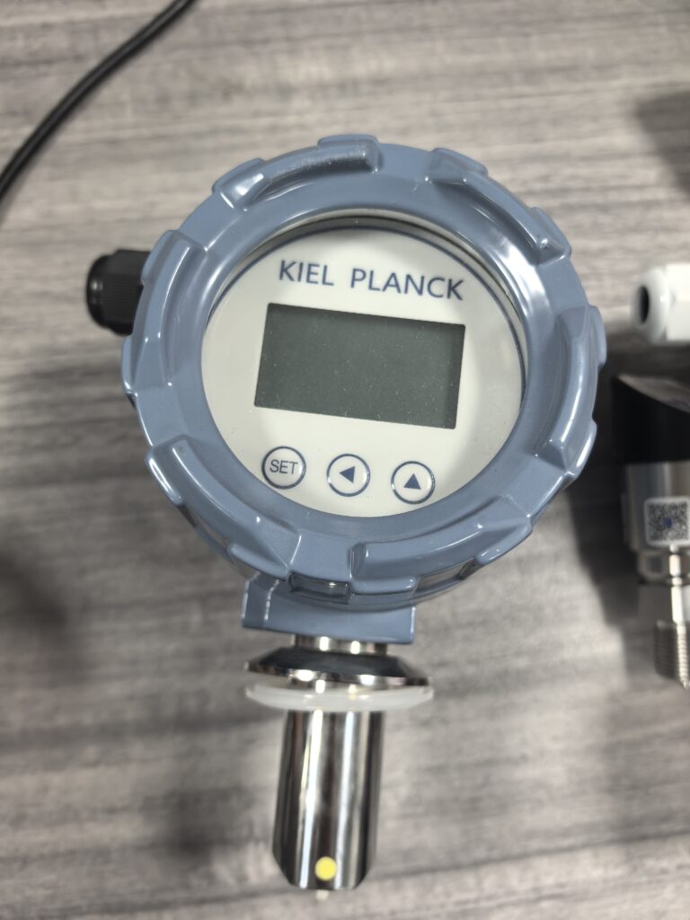
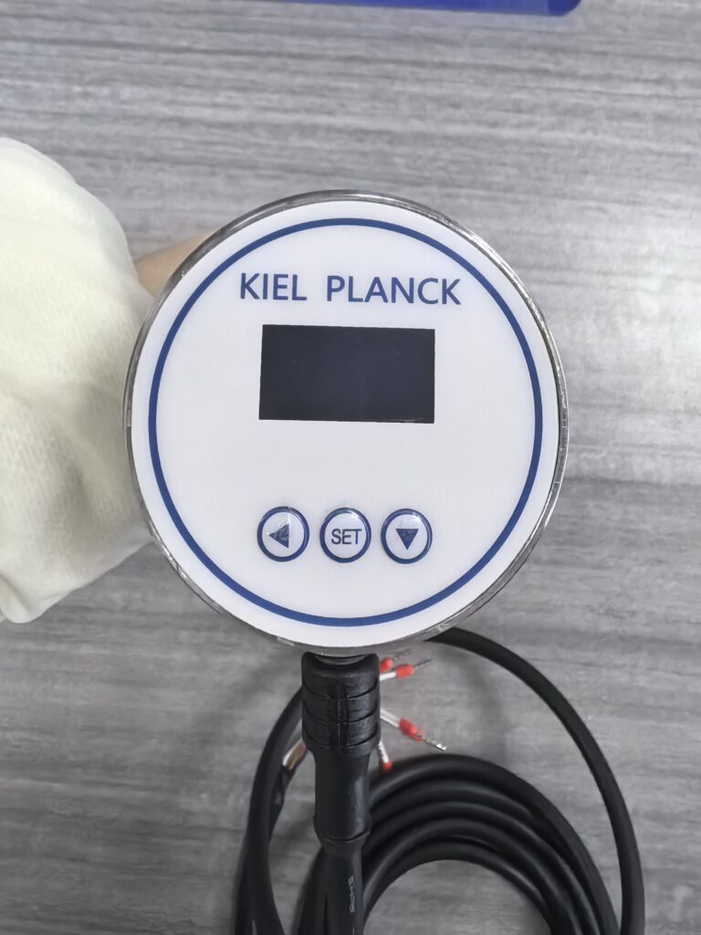
The secondary display transmitter is responsible for signal processing and data output, including a signal amplification circuit, microprocessor, display screen and data transmission interface. The weak pulse signal collected by the sensor is amplified, filtered and shaped by the circuit to eliminate interference signals generated by pipeline vibration and fluid fluctuation. The microprocessor calculates the effective flow data according to the preset instrumental constant, and finally displays the instantaneous flow and cumulative flow in real time through the display screen. Meanwhile, it can output standard electrical signals to realize remote data transmission and automatic monitoring.
In addition, the flowmeter is equipped with sealing gaskets and fixed connectors to prevent fluid leakage and avoid external environmental interference. Compared with other types of flowmeters, the structural design of impeller flowmeters is more compact and reasonable, with low failure rate and strong adaptability. However, it has certain application limitations, such as being unsuitable for high-viscosity fluid and impurity-containing fluid measurement, which is easy to cause blade adhesion and jamming and affect measurement accuracy.
In conclusion, impeller flowmeters realize accurate fluid flow measurement through the mutual matching of fluid kinetic energy conversion principle and modular structural components. Its simple working mechanism and reliable structural design lay a solid foundation for its popularization in industrial measurement. In practical application, matching the working principle and structural characteristics with the measurement medium and working conditions can give full play to its measurement advantages and ensure the long-term stable and accurate operation of the instrument.
Scan the QR code to receive more detailed information.





