

This paper systematically elaborates on the basic measurement principles of radar level meters, including the core time-of-flight theory, two mainstream technical mechanisms of pulse radar and frequency-modulated continuous wave (FMCW) radar, as well as the signal calculation logic. It also briefly analyzes the technical advantages and application characteristics of radar level measurement. The study aims to provide a clear theoretical reference for the understanding and practical application of radar level detection technology in industrial production.
1. Introduction
Liquid level monitoring is a core link in industrial process control, which is crucial for ensuring production safety, optimizing material inventory and maintaining process stability. Traditional level measurement methods such as floating ball and ultrasonic measurement are limited by temperature, pressure, vapor and dust interference, resulting in reduced measurement accuracy and unstable operation in complex industrial environments. As a non-contact measuring technology, radar level meter effectively overcomes the above limitations. It relies on microwave electromagnetic wave transmission and reflection to realize real-time and high-precision level measurement, and has become the mainstream measuring equipment in petrochemical, pharmaceutical, water treatment and other industries.
2. Core Measurement Principle
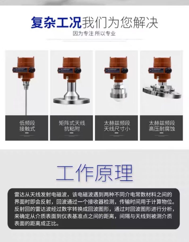
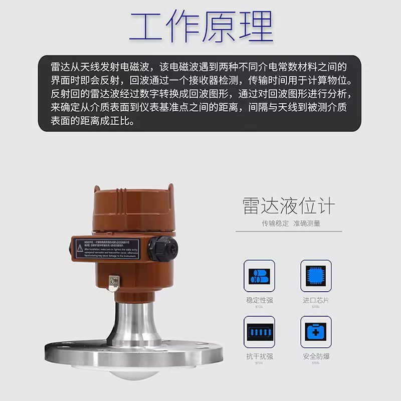
The fundamental working principle of radar level meters follows the time-of-flight (TOF) theory of electromagnetic waves. The device emits high-frequency microwave signals through its antenna, which propagate downward at the speed of light. When the microwaves reach the surface of the measured medium (liquid or solid), they are reflected back due to the difference in dielectric properties between air and the medium. The antenna receives the reflected echo signal, and the built-in microprocessor calculates the distance between the instrument and the medium surface by accurately measuring the round-trip time of the microwave signal.
The core calculation formula for level measurement is universally applicable: D = (c × t) / 2. In this formula, D represents the vertical distance from the radar antenna to the medium surface, c refers to the propagation speed of electromagnetic waves in the air (approximately 3×10⁸ m/s), and t is the round-trip time of the microwave signal. After obtaining the distance D, the system subtracts this value from the total height of the tank to calculate the real-time height of the medium level, completing the measurement process.
3. Two Mainstream Radar Measurement Technologies
According to different signal transmission modes, radar level meters are mainly divided into pulse radar and FMCW radar, both of which follow the basic electromagnetic wave reflection principle but differ in signal processing methods.
Pulse radar level meters transmit intermittent microwave pulses. The sensor records the time difference between pulse emission and echo reception, and calculates the level height through the TOF formula. This technology has simple structure, low cost and stable performance, which is suitable for most conventional industrial measurement scenarios.
FMCW radar level meters transmit continuous microwaves with linearly changing frequencies. When the reflected signal returns, a frequency difference is formed between the transmitted wave and the echo wave. The frequency difference is positively proportional to the propagation distance of the signal. The microprocessor converts the frequency difference data into level values through algorithm calculation. Compared with pulse radar, FMCW radar has higher measurement accuracy and stronger anti-interference ability, and is more suitable for high-precision measurement scenarios such as high-pressure, high-temperature and turbulent liquid surfaces.
4. Technical Advantages of Radar Level Measurement
Radar microwaves are insensitive to environmental factors such as temperature, pressure, dust, steam and chemical corrosive gases, so radar level meters can work stably in extreme working conditions. Meanwhile, the non-contact measurement mode avoids mechanical wear and medium adhesion, reducing equipment failure rate and maintenance cost. In addition, with the optimization of antenna structure and signal processing algorithms, modern radar level meters can effectively filter false echoes generated by tank walls, obstacles and foam, further improving measurement reliability.
5. Conclusion
In summary, the measurement of radar level meters is based on the time-of-flight principle of high-frequency electromagnetic waves, and realizes accurate level calculation through signal emission, reflection, reception and intelligent algorithm processing. Pulse radar and FMCW radar technologies complement each other in application scenarios, covering conventional and high-precision industrial measurement demands. With the advantages of strong environmental adaptability, high accuracy and low maintenance, radar level measurement technology has irreplaceable value in modern industrial automation. In the future, with the continuous upgrading of signal processing and intelligent identification technology, radar level meters will achieve higher measurement precision and richer functional expansion, and be more widely used in industrial intelligent monitoring systems.
Scan the QR code to receive more detailed information.





