

These core differences lead to distinct performance in precision, anti-interference capability, and adaptability to different media. This paper systematically compares the structural characteristics, working principles, and medium adaptation ranges of the two radar technologies, clarifies their core application differences, and provides a scientific basis for industrial equipment selection under diverse working conditions.
1. Introduction
Radar level measurement has replaced traditional mechanical and ultrasonic measuring methods in most industrial scenarios due to its high stability and environmental tolerance. According to different signal transmission modes, radar level meters are divided into guided wave radar and non-contact radar. Many industrial users fail to select appropriate equipment due to unclear understanding of their core differences, resulting in low measurement accuracy or frequent equipment failure. Therefore, analyzing the differences in structure, working principle and medium adaptation of the two radars is crucial to give full play to the advantages of radar level measurement technology.
2. Structural Differences
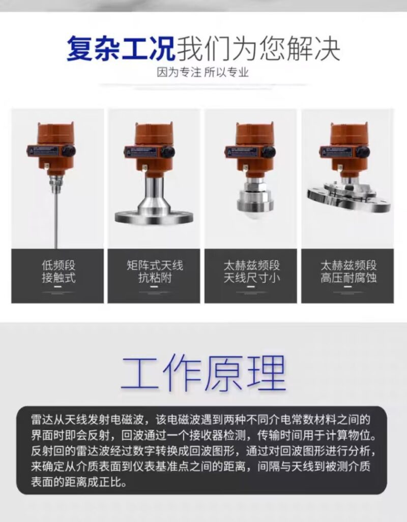
The structural gap is the most intuitive core difference between the two devices. Guided wave radar level meters are typical contact measuring instruments, mainly composed of a transmitter, a signal processing module and a rigid or flexible probe. The probe extends vertically into the measured medium and serves as a fixed transmission carrier for microwave signals. The overall structure is compact, with strong anti-vibration performance, and it can adapt to narrow space working conditions such as small-diameter tanks and complex pipeline containers.
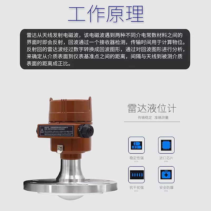
In contrast, non-contact radar level meters adopt a fully non-invasive structural design, consisting of an antenna, a signal transmitter and a processor without any contact components extending into the container. The antenna is installed at the top of the tank, emitting microwaves downward through air. The structure is simple and free of mechanical wear. Since there is no probe contact, the equipment avoids medium adhesion, corrosion and impact damage, making it more suitable for high-cleanliness and severely corrosive working environments.
3. Working Principle Differences
Both technologies follow the time-of-flight theory, but their signal transmission mechanisms are completely different. Guided wave radar transmits high-frequency microwave pulses along the surface of the built-in probe. The microwaves propagate along the probe at a stable speed, and generate obvious reflection signals when encountering the interface between air and medium. The processor calculates the level height by measuring the round-trip time of the guided waves. The guided transmission mode effectively avoids signal divergence and loss, with extremely high signal stability.
Non-contact radar emits free-propagating microwaves through the antenna, which spread downward in a conical shape in the air. The microwaves are reflected on the medium surface and received by the antenna. Its measurement relies on free-space signal transmission. However, the signals are prone to divergence and interference from steam, dust and foam in the air, resulting in weaker echo signals compared with guided wave radar and slightly lower measurement stability in complex environments.
4. Medium Adaptation Differences
Guided wave radar has outstanding adaptability to low-dielectric constant media, including light oil, gasoline, kerosene and low-density solid particles. The probe-guided signal transmission can effectively capture weak interface echoes that non-contact radar cannot identify. It is also applicable for viscous media and layered liquid measurement. Nevertheless, it is not suitable for highly corrosive, easy-crystallization and high-purity sterile media, as probe contact will cause adhesion, corrosion or medium pollution.
Non-contact radar is ideal for high-dielectric, corrosive, viscous and easily polluting media such as strong acid, strong alkali and high-viscosity slurry. Without probe contact, it completely avoids medium adhesion and secondary pollution. It also adapts to high-temperature and high-pressure volatile media with a large amount of steam and foam. However, it performs poorly in measuring low-dielectric media, with weak echo signals and low measurement accuracy.
5. Conclusion
In summary, guided wave radar and non-contact radar have irreplaceable advantages due to their structural and principled differences. Guided wave radar features guided signal transmission, high precision and stable performance, and is suitable for low-dielectric, layered and narrow-space measurement scenarios. Non-contact radar adopts non-invasive structure, free from medium corrosion and pollution, and is applicable for corrosive, volatile and high-cleanliness media. In practical industrial applications, users should select equipment based on medium characteristics, tank conditions and measurement requirements to ensure optimal measurement accuracy and operational stability.
Scan the QR code to receive more detailed information.





