

The study aims to provide systematic technical guidance for the configuration of water flow switches in vacuum sintering furnace systems, effectively avoid equipment overheating damage and production safety accidents caused by abnormal water flow, and improve the long-term operational reliability of sintering equipment.
1. Introduction
Vacuum sintering technology is widely used in powder metallurgy, ceramic manufacturing and new material processing industries, featuring high temperature, high vacuum and high precision processing characteristics. During continuous operation, the furnace body, heating elements and sealing components will produce massive heat, which must be timely taken away by the circulating cooling water system to maintain constant equipment operating temperature. Once the cooling water flow is insufficient, interrupted or blocked, local overheating of the furnace will occur, leading to seal failure, component burnout, and even scrapping of sintered products and safety accidents.
Water flow switches are pivotal safety protection devices for cooling water systems. They can monitor real-time water flow velocity and flow rate, and trigger alarm signals or linkage shutdown actions through the PLC control system when the flow value is lower than the safe threshold. Different from conventional industrial water systems, the cooling water of vacuum sintering furnaces is prone to scale, rust and suspended particle accumulation under long-term high-temperature heat exchange. Therefore, strict pertinence is required in the selection and installation of flow switches to adapt to harsh industrial working conditions and ensure long-term stable monitoring performance.
2. Key Selection Principles of Water Flow Switches
The selection of water flow switches for vacuum sintering furnace cooling systems should comprehensively consider system working parameters, water quality characteristics and safety protection requirements, focusing on the following core indicators.
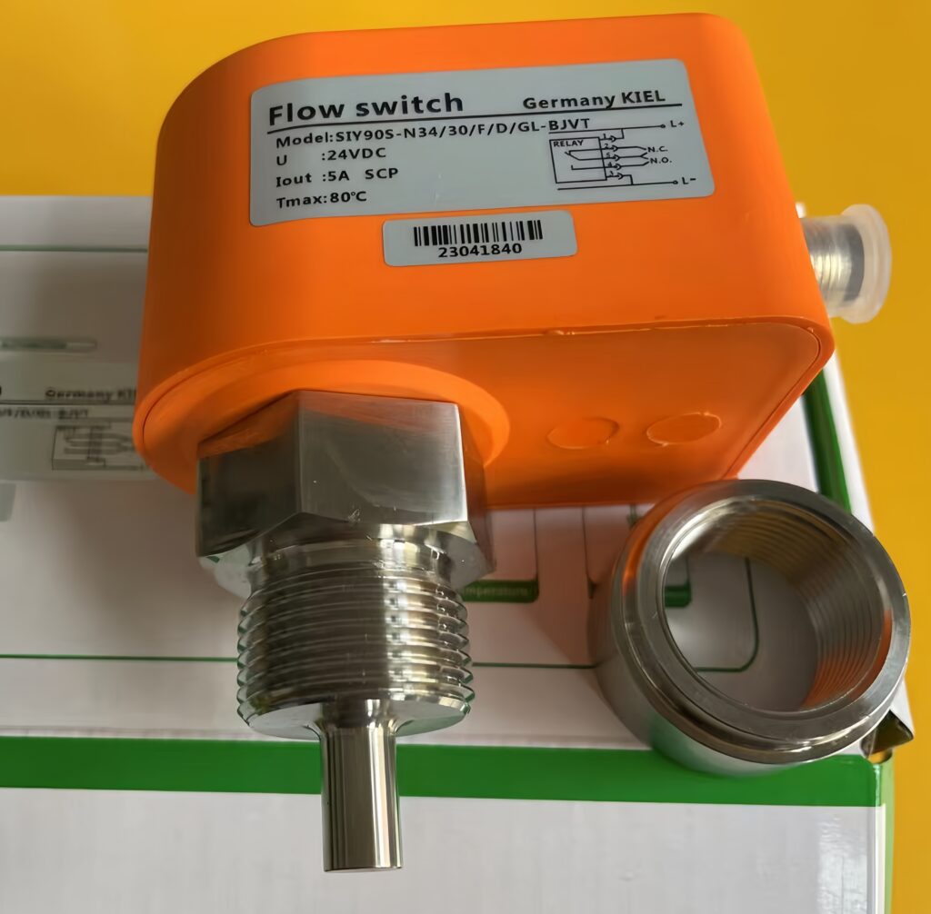
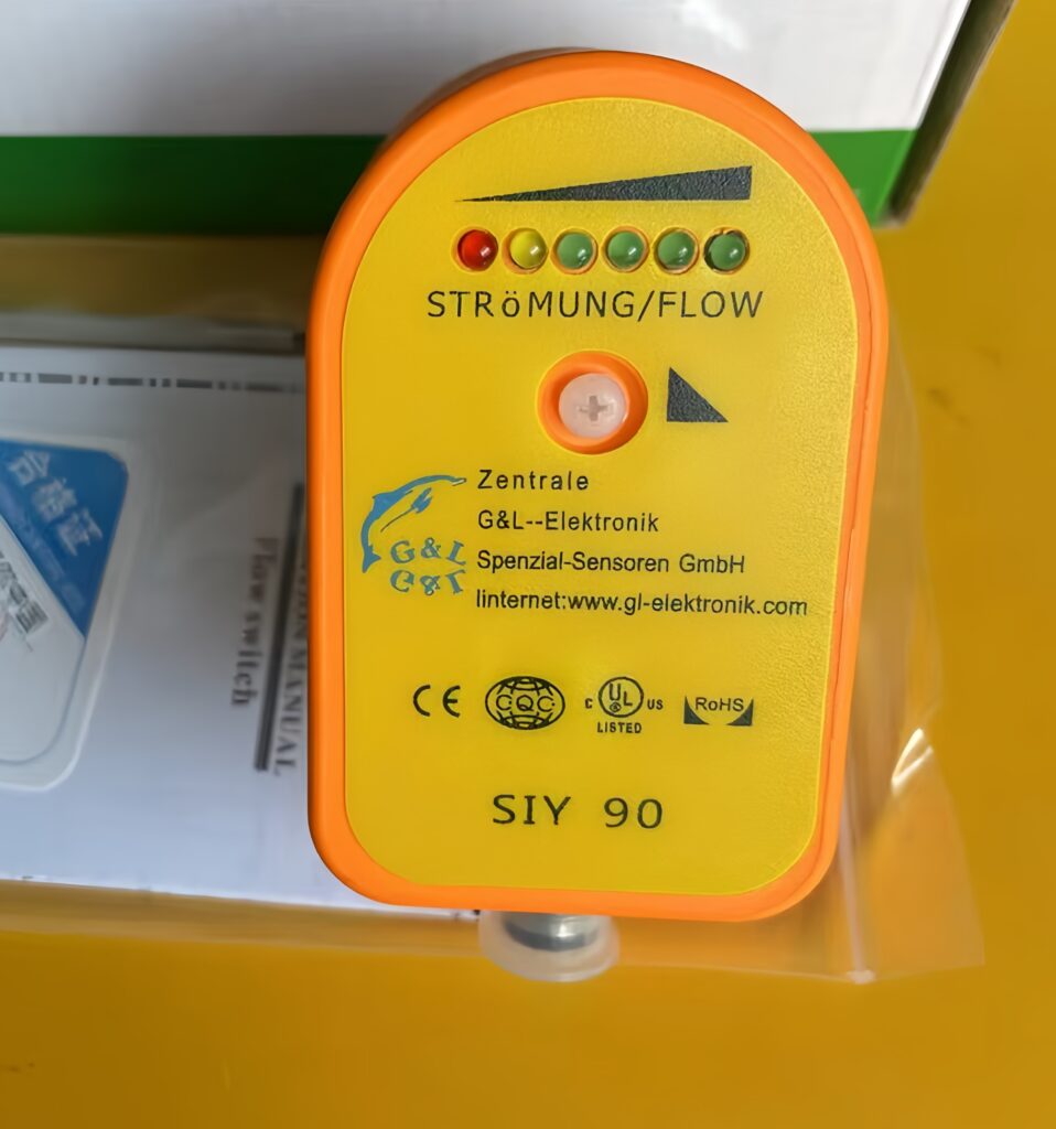
First, adaptability to working conditions and water quality. Traditional mechanical paddle flow switches are equipped with movable parts, which are easily stuck by scale and suspended impurities in cooling water, resulting in detection failure. For high-temperature circulating water environments of sintering furnaces, thermal dispersion flow switches without movable parts are more suitable. This type of switch monitors flow changes through temperature difference sensing, with anti-blocking and anti-corrosion performance, and can stably operate for a long time in impurity-containing industrial water.
Second, matching of flow range and system parameters. The rated flow threshold of the switch must match the designed circulating water flow of the sintering furnace. The minimum trigger flow should be slightly lower than the system’s safe operating flow to ensure timely alarm for insufficient flow, while avoiding false alarms caused by normal flow fluctuation. Meanwhile, the switch pressure resistance and temperature resistance grades must meet the system’s maximum working pressure and water temperature to prevent equipment damage under extreme working conditions.
Third, compatibility of signal output and control system. The flow switch should support standard relay signal output, which can be seamlessly connected with the furnace’s PLC control system to realize automatic alarm, cooling pump stop and furnace heating shutdown linkage functions. In addition, the shell material should adopt high-quality brass or stainless steel with RoHS compliance, featuring good corrosion resistance and high-temperature resistance to adapt to the humid and high-temperature operating environment of the furnace workshop.
3. Standard Installation Specifications and Technical Points
Even high-quality flow switches will suffer from reduced detection accuracy and frequent failures due to non-standard installation. The installation of flow switches in vacuum sintering furnace cooling systems must follow standardized piping and construction specifications.
The first key point is the selection of installation position. The switch must be installed on a straight pipe section, avoiding elbows, valves, reducers and other pipe fittings that easily cause flow turbulence. It is required to reserve a straight pipe section of no less than 5 times the pipe diameter upstream and 3 times the pipe diameter downstream to ensure stable water flow and accurate detection data. The installation direction must be consistent with the water flow direction, strictly aligning with the flow direction arrow marked on the switch shell, and vertical or horizontal installation can be selected according to on-site piping conditions.
The second key point is standardized construction and wiring. During installation, a hexagonal wrench should be used for fixing to avoid excessive force damaging the switch thread and shell. Sealing gaskets must be installed at the pipeline connection to prevent water leakage, which will affect system pressure and flow stability. For electrical wiring, DC24V industrial power supply is adopted, and normally open or normally closed contacts are selected according to the control system design. Wiring must be firm and waterproof, with redundant wires properly arranged to avoid abrasion and short circuit caused by equipment vibration.
The third key point is post-installation commissioning and calibration. After installation, pipeline flushing must be carried out first to remove residual impurities in the pipe to prevent blockage. Then, flow calibration is performed to adjust the switch sensitivity and trigger threshold according to the actual operating flow of the cooling system. Finally, a simulation test of flow interruption and insufficient flow is conducted to verify that the switch can accurately trigger alarm and linkage protection actions, ensuring reliable system protection functions.
4. Daily Maintenance and Fault Prevention
To maintain long-term stable operation of the flow switch, regular daily maintenance is essential. It is necessary to regularly clean the switch probe and pipeline dirt to prevent scale accumulation from affecting sensing accuracy. Regularly inspect wiring tightness and shell integrity to avoid failure caused by water inflow and circuit aging. In addition, seasonal calibration should be carried out to adapt to flow changes caused by temperature variation, ensuring the detection sensitivity of the switch in different working environments.
5. Conclusion
Water flow switch is an indispensable safety barrier for the cooling water system of vacuum sintering furnaces, and its scientific selection and standardized installation are the key to ensuring the safe and stable operation of sintering equipment. In terms of selection, priority should be given to non-movable part anti-blocking flow switches matching system flow, pressure and temperature parameters to adapt to the harsh water quality and working conditions of industrial circulating water. In terms of installation, standard straight pipe section layout, directional installation and standardized wiring commissioning must be strictly implemented to eliminate detection errors and potential safety hazards caused by non-standard construction. Combined with regular daily maintenance and calibration, the monitoring accuracy and operational stability of the flow switch can be effectively guaranteed. This not only avoids equipment damage and production losses caused by cooling water flow abnormalities, but also provides a reliable technical guarantee for the high-precision and safe production of vacuum sintering processes.
Scan the QR code to receive more detailed information.





