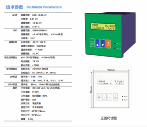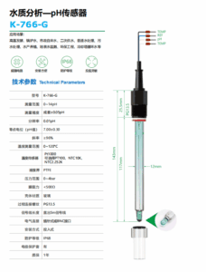
An integrated temperature transmitter consists of a resistance temperature detector (Pt100) or thermocouple sensing element, a transmitting circuit, and a protective sheath. It is a commonly used temperature measuring instrument in industrial settings.

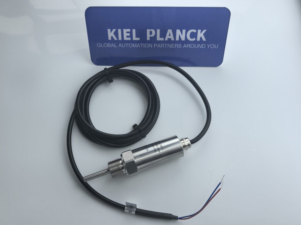
I. Product Overview The integrated temperature transmitter consists of a Pt100 resistance temperature detector (RTD) or thermocouple sensing element, a transmitting circuit, and a protective sheath. It is a commonly used temperature measuring instrument in industrial settings. The device converts the weak resistance or millivolt thermoelectric signal from the sensor into a 4-20mA standard DC current signal, compatible with PLCs, digital displays, and DCS control systems. It is widely used for temperature monitoring in industries such as heating, chemical, power, water treatment, and metallurgy.
Based on the sensing element, it is divided into two main categories: Pt100 RTD type and thermocouple type. Pt100 RTD transmitters rely on the linear change of platinum wire resistance with temperature to measure temperature, offering high measurement accuracy, good low-temperature stability, and a temperature range mostly from -200℃ to 600℃. Thermocouple transmitters utilize the thermoelectric potential of two metals for temperature measurement, are resistant to high temperatures, and can measure temperatures above 600℃. The integrated structure encapsulates the transmitter module within the temperature probe junction box, resulting in a compact size that eliminates the need for separate on-site installation. Its anti-interference capability is superior to that of separate transmitters. Power is typically supplied via a DC 24V supply, making it a two-wire instrument with simple wiring, suitable for long-distance signal transmission, and the voltage drop across the line does not significantly affect measurement accuracy.
II. Classification and Working Principle
Two-wire transmissions are the current mainstream structure. Power and signal share two wires. When powered by DC 24V, 4mA corresponds to the lower limit of the measurement range, and 20mA corresponds to the upper limit. The intermediate temperature varies linearly with the current. A few older products use three-wire or four-wire RTD transmitters, mostly used for high-precision laboratory temperature measurement. The transmitter’s internal circuitry performs signal amplification, linear correction, cold junction compensation, and V/I conversion. The compensation circuit can offset measurement errors caused by changes in ambient temperature, ensuring stable temperature data.
III. Standard Wiring Method
1. Two-Wire Universal Wiring (Most Common)
When the two terminals in the instrument junction box are not marked with positive and negative polarity, connect one end of the two cables to the two terminals of the transmitter, and the other end to the control system:
1. DC24V power supply: Connect the positive terminal to the PLC or instrument power supply terminal, and the negative terminal in series with the acquisition input terminal. The current signal is formed by the loop, and the loop current of 4-20mA is directly read by the acquisition module. Shielded cables are preferred for wiring, with the shield grounded at one end. Keep away from power cables such as inverters and motors to avoid electromagnetic interference causing data fluctuations.
2. Pt100 Three-Wire Transmitter Wiring: The three leads are one compensation wire and two resistance wires. The terminals are marked A, B, B. Short-circuit the two B-terminals of the same color and connect them to the instrument. Connect the A terminal separately to compensate for measurement errors caused by the resistance of the line conductors. This is suitable for applications with long wiring distances. A four-wire system adds one more lead to the three-wire system, completely eliminating line resistance. This is often used for precision temperature measurement.
3. Thermocouple Transmitter Wiring: Distinguish between positive and negative terminals. The polarity of the thermocouple compensation wires must not be reversed. Incorrect polarity connection will result in lower readings or fixed values. The compensation wires must be selected and matched according to the calibration number; ordinary copper wires must not be mixed.
IV. Wiring Precautions Avoid high-temperature pipes and corrosive media when wiring. Run cables through conduits for protection to prevent wear, damage, and short circuits. Secure wiring terminals firmly to avoid loose connections that could cause signal instability. Never connect to AC 220V; instantaneous high voltage can damage the transmitter circuit board. After installation, perform a no-load test. The output should be approximately 4mA without heating media; the current should increase synchronously with temperature rise. Confirm that the wiring is correct before putting the device into use. Proper wiring ensures accurate measurements and significantly reduces the frequency of future malfunctions.
Scan the QR code to receive more detailed information.